Einleitung

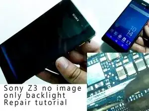
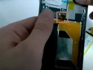
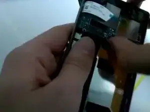
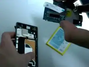
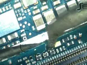
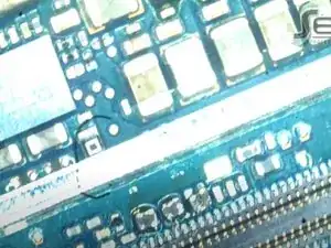
If your Sony Xperia Z3 smartphone shows no image but the backlight is working, there may be a problem with the phone’s logic board. This problem can occur because of failed screen replacement attempts. Use this guide to repair your device.

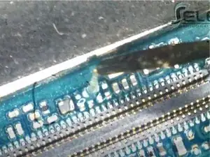
Alternatively, see this Sony Xperia Z3 no image after screen replacement YouTube video for help micro-soldering the logic board.

Sony Z3 no image after screen replacement only backlight Hardware Repair

  1. IBVhVNAcgUXkELdR
    IBVhVNAcgUXkELdR
    6JK4olH1QPKLLwOa
    HUQ2FtAZb6BU55OX
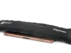
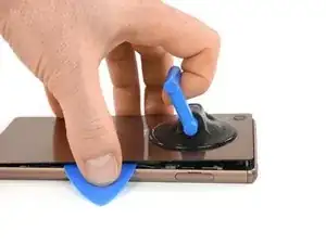
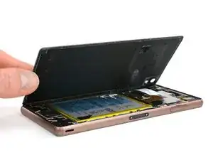
    • Heat the back cover of your Xperia Z3 to loosen the adhesive underneath.

    • If you use an iOpener, follow these instructions for use.

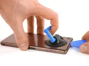
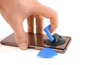
    • Lift up the back cover with a suction handle and put an opening pick in the gap.

    • Move the pick carefully around the edges to loosen the adhesive on every side of the phone.

    • Don't put the pick in too deep under the back cover to not damage any parts inside the phone.

    How hot (how many C) should the iOpener be? I think it would be safer / more accurate to heat the iOpener in an oven with accurate temperature control.

    Magnus Myklebost -

    Careful here. The back cover cracked in two places. Once when I exerted pressure with the suction handle, and in the corner when moving the pick around the edges- even though I was very gentle. The battery was adhered firmly to the back cover.

    Joseph Doyle -

    I cracked the back cover instantly. Make sure to buy a spare one before opening!

    raffaelecaroppo -

  2. gAPs2OKNE2jFrYEo
    gAPs2OKNE2jFrYEo
    ZWXMfEZUoFXZNtsY
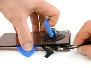
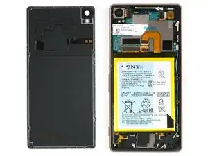
    • There are two adhesive strips in the center of the phone connecting the rear case to the battery, you'll need to remove them to open the phone.

    • When the edges of the cover are free from adhesive, tilt it to allow access to the battery tabs.

    • Use tweezers to pull the two black adhesive strips out of the phone but don't pull just yet.

    Careful during this bit. My old Z3 back cover couldn’t take it and split into lots of pieces (probably weakened over the years!). Just order a replacement for £3 off ebay before doing it ;-)

    Bruce Wiggins -

    Merci pour ce tuto. Excellente procédure. Travaux réalisés en 20 minutes sans aucun problème. Attention: au remontage, il n'y a plus d'adhésif sur la batterie, la coque arrière peut éventuellement tomber. Je ne l'ai pas fait mais il faut peut-être mettre un petit double face sur la batterie.

    Patrick Prel -

  3. InbaMOV3DWrHJVIa
    InbaMOV3DWrHJVIa
    meP2FFCEEUXJ2oL1
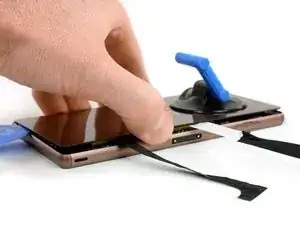
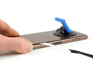
    • Gently pull out both of the adhesive tabs out of the phone, parallel to the rear cover.

    • If the adhesive tabs break, try to use a thin flat plastic tool such as a plastic card to remove the last of the adhesive. If the adhesive is stubborn, heat it with an iOpener or hair dryer and pry again.

  4. RaESkTApChpTNMDs
    RaESkTApChpTNMDs
    Fut6DNQrqXXALvsP
    • After pulling out the adhesive tabs, you can lift the back cover and remove it.

  5. oDgQiiMN4YTyHo2E
    oDgQiiMN4YTyHo2E
    jgVRsCU2JSMV5Ufd
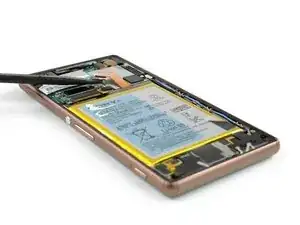
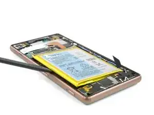
    • Unplug the battery flex connector.

    • Use a tweezer to gently pull off the adhesive strip on the bottom part of the battery.

  6. RKmlYKT6k54PTcuC
    RKmlYKT6k54PTcuC
    XUTjqjATMmWYD61p
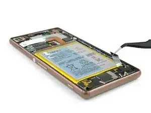
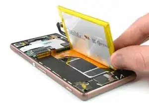
    • Use a spudger on the left side of the frame to lever out the battery.

    • Be careful with the spudger - there are cables beneath the battery!

    • Remove the battery.

  7. vBFRvAiXTjOmMIbx
    vBFRvAiXTjOmMIbx
    EtU1liOTqUxPT4MY
    WjxKt31xfhXTM4uD
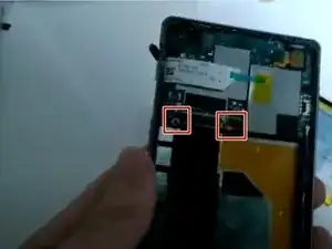
    • Use your fingers or the flat end of a spudger to unclip the cables holding the logic board in place.

  8. 46NIXSc6rKXEDtdB
    46NIXSc6rKXEDtdB
    P5omh6TmFFA4KSoA
    HKSvfoUVOHEgcO4b
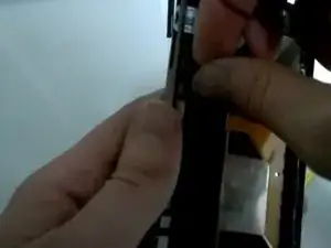
    • Use your fingers to remove the phone's logic board.

    • Visually inspect the logic board.

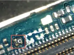
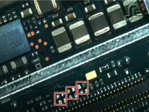
    • This logic board is missing filters, which were likely damaged when the user attempted to replace the phone's display.

  9. JT1YcKsGyVKVqk3D
    JT1YcKsGyVKVqk3D
    TchxMhTMddIkJMaU
    pXIVuR4AOiYGNyYD
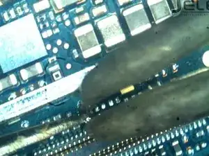
    • Apply a small amount of flux to the motherboard's filters.

    • In micro-soldering, flux prepares the metal surfaces of the logic board by cleaning and removing impurities.

    • Wait at least 30 seconds for the flux to clean the surfaces.

    • Use a pair of micro-soldering tweezers to remove the metal square from the filters.

  10. k3KPRUCcvdAIcmYJ
    k3KPRUCcvdAIcmYJ
    4FWIGbMvQVVJGoYb
    HAgQaTiKkSnGIUNZ
    • Apply solder to each of the three sets of four pins now exposed on the logic board.

    • After each solder, apply a small amount of flux to the new connection to clean the connection.

    • Be sure to wait at least 30 seconds after applying the flux so that it can clean and remove impurities.

  11. ceRf6OvMZaMHSLB2
    ceRf6OvMZaMHSLB2
    C1eedKeKKltvkSCY
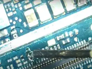
    • Check that each of the connections covers all four of the pins in each set.

    • Re-form the solder or add additional solder if the connection does not cover all four pins.

Abschluss

To reassemble your device, follow these instructions in reverse order.

Alex Sander

Mitglied seit: 28/02/17

37529 Reputation

2 Kommentare

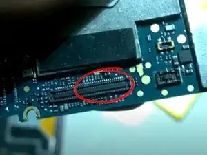
I have a z3 single, it turns on the backlight but not the image what to do? procedure above did not work …

keneddy.s.2011 -

i &&^&@@ my display
ahmedelbahri -