Einleitung

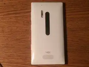
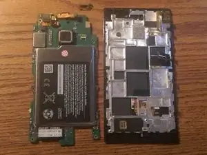
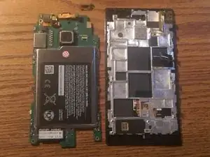
This guide shows how to remove the motherboard from the Nokia Lumia 928.

  1. jHikV4PVfCi4Jeai
    jHikV4PVfCi4Jeai
    jaKwENYNEEAVfKEs
    uoaHNVWkQo5YBrRf
    • Start by powering off the phone.

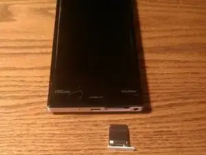
    • Next remove the sim card tray.

    • Once sim tray is removed you can now remove the T5 screw from the sim card slot.

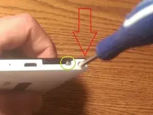
    • Now insert the T5 screwdriver into the headphone jack. There is a T5 screw in the headphone jack that has to be loosened.

    • The screw in the headphone jack does not come out, so do not try to remove it. Nokia uses a lock bar on this case that locks the plastic clips in place. So the screw in the headphone jack is how you loosen and tighten the lockbar. You will break the back case trying to remove it if you are unaware of the lockbar and do not loosen it first.

  2. KM6OhROjPbQVsbcJ
    KM6OhROjPbQVsbcJ
    ABCCWA1jjU5vNjaN
    l1EofffjKnq5vdSI
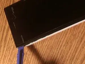
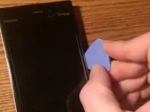
    • Now with the lock bar loosened you can begin using your pry tool to free the plastic clips that hold the back case in place.

    • I find it easiest to start at the top left corner and work down to the bottom left corner. Then move to the top of the device and work your way around and down the right side of the device. I then free up the bottom last. Seems the guitar pick works great to free the plastic clips.

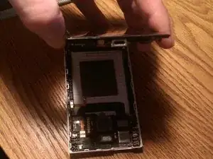
    • Once the clips are free you can then pull the back case off.

  3. QAHExqsMFLobShZ2
    • You have now removed the back case.

    • To reassemble follow these directions in reverse order.

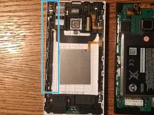
    • The area highlighted in blue in the picture is where the lock bar resides.

  4. 34UaJXefVTFM5Z1K
    34UaJXefVTFM5Z1K
    1OKnAJyCdpq2lGwA
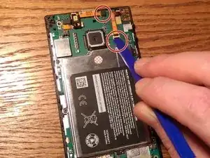
    • First free all ribbon cables from their connections on the motherboard.

    • The two areas circled in red are where the ribbon cables connections need to be freed from the logic board.

    • Free the ribbon cables from the logic board with a plastic pry tool.

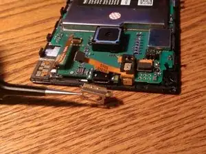
    • Now that the ribbon cable connections are free you will now need to remove a metal clip around the usb port.

  5. tcUDsYmaAN6edYJM
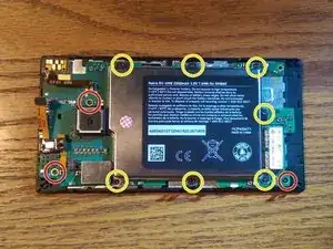
    • Now we can begin by removing the 10 T5 screws from the motherboard.

    • The ten screws appear to be the same size. But to be safe try to keep the screws circled in red and yellow separate.

  6. CPfDOYhjRKquwwOi
    CPfDOYhjRKquwwOi
    sDQvt1UVunOQFpqV
    IFWXksq1duFixTL1
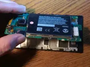
    • With all ten T5 screws removed we can now lift from the left side of the motherboard. that needs freed

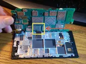
    • The area in yellow is the only connection on the underside of the motherboard that needs to be freed up. This is the display connection.

    • Pry the connection loose from the motherboard with a plastic pry tool.

    • Now you can remove the motherboard.

Abschluss

To reassemble your device, follow these instructions in reverse order.
BurnieG

Mitglied seit: 23/02/15

10753 Reputation

0 Kommentare