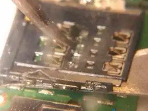
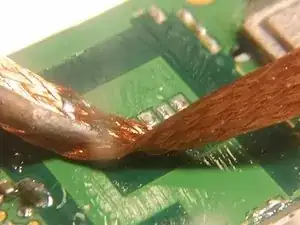
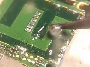
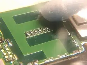
Einleitung
Inspired by the recent microsoldering series with Jessa Jones, and since I have dabbled with the concept of micro soldering a tad bit myself, I figured: Why not make a guide about it? There is an obvious lack of SMD guide content here on iFixit, and this guide, while being novice made, can be of some assistance to someone just starting out on cellphone motherboard soldering. It would be an honor to have someone as renowned as Jessa see this, and comment on what I am doing right and/or wrong, to help me improve.
So, by no means is this a professional-made guide, as you can see from the general look and feel to the guide. This is a more practical approach, without overly sophisticated wording and such. This guide, and its flaws, could, however, be an inspiration to some professional for making a better guide on this.
The key to this repair - like with all microsoldering, in my opinion - is inspection. You will be examining the device carefully at each step. And please note: If you see no visible damage done to the SIM card slot, consider other possiblities. For example, set time right on IOS to have the phone ask you for PIN code. Use common sense: if you feel like you should not be doing something like this, don't.
Think first, then act.
Watch these videos for extra knowledge, if you are feeling unsure at this point:
https://www.youtube.com/watch?v=w1UxrNav...
And familiarize yourself with the disassembly of this device:
Huawei Ascend P6-U06 Motherboard Replacement
Also, read this guide in its entirety before actually starting the repair.
Werkzeuge
-
-
Most damaged SIM-readers can be determined broken without disassembling the device. If the SIM problem persists despite external signs of damage, disassembling the device is in order.
-
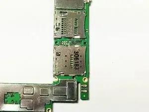
Follow the steps in the P6 motherboard replacement guide Huawei Ascend P6-U06 Motherboard Replacement to disassemble the device. At this point, you should have a good view inside the sim slot.
-
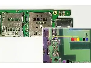
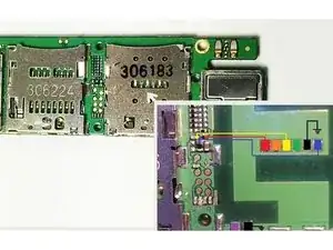
You can also measure continuity between the points marked in the crude schematic, however, this only tells you whether the motherboard is functional regarding the SIM ways.
-
-
-
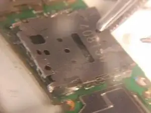
Add kapton/aluminum foil around the part to prevent heating other components, and using an iron or a heatgun, start undoing the sim-reader shield's attachment points from logic board. Gently pry up with tweezers and hold the shield up after it pops out of each attachment point.
-
Release after solder has solidified, to avoid accidental reattachment. Go around the shield, being careful to not pry too hard until solder has melted, otherwise you will pull pads.
-
You can also cut the old reader shield into smaller pieces with scissors, to make the removal process easier.
-
-
-
After removing the shield, take out (and save, just in case you lose a part) the sim eject mechanism parts, and then take an exacto knife, and slide it under the sim card reader. Melt the first solder joint on the reader, sliding the knife in between the pad and the leg of the reader to prevent it from soldering itself back on.
-
Proceed with the desoldering, whilst advancing with the knife further under the reader. Finally, once all 6 legs are done, do the same with the two remaining legs, being extra careful with the left one (the right being ground). After this, the reader should come off without further prying. If not, check for intact solder joints.
-
Better pictures are welcomed, add yours if you attempt this.
-
-
-
After removing the reader altogether, I would recommend adding a little bit of flux, and using solder wick, removing all old solder, and then taking a small blob of solder (mind the heat of the iron) rolling that ball of solder on the pads with sufficient amount of flux to tin the pads with new solder. Don't overdo this, or pads will come off.
-
Excessive solder has to be removed, though. Like that blob on the left hand side, next to the capacitor, which is remnants of desoldering. Sometimes it helps to replace the lead-free solder or just add more leaded solder to melt the joint.
-
-
-
Now the pads ought to be cleaned. Use isopropyl alchohol, or ethanol and some q-tips to do this. I know there are some fibers in the picture. This is the reality, though. Without professional tools, fibers do happen, but you can just remove them afterwards. The other picture should give you a good idea of how important the cleaning part is.
-
-
-
At this point I recommend testing the area around the sim card reader on the motherboard. If you have a microscope, after proper cleaning it should be easy to check for bad pads, lost components, anything out of the ordinary.
-
Also perform a check with multimeter, using the continuity test mode, to see if the pads actually lead to where they should.
-
There should be no continuity between any two pads, except for the two ground pads (marked black in the picture). I jotted down a few resistance values for resistances between the pads, in case somebody needs to know them (they are approximates, apparently there is variance to this)- if you need to know these, send me a message.
-
-
-
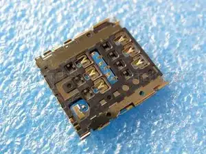
The next step is to solder the new part into place. I recommend taking apart the new part: it is easier to solder the six legs of the reader in the middle (pic?) if you remove the shield on top. This way you will have to put together the sim eject mechanism later on, but imo it's worth it.
-
Now, the alignment of the sim reader is of paramount importance. If the reader is misaligned, it will cause problems and misery later on. A good rule of thumb: if all the legs are in place over the pads and in the middle, you're good to go. Also, make sure you leave the surrounding ground pads for the shield visible.
-
-
-
This is the tricky part. You should probably use a small pinching clip to hold the sim reader in place, and if you haven't got much experience with micro soldering, I strongly advice using two hands to steady your iron.
-
Apply a small amount of flux onto the legs and pads, and then touch one pad. At this point, having a microscope comes in handy, because you can see the solder melt.
-
After that just proceed touching the legs one by one, soldering all 8 legs onto the logic board.
-
-
-
After you're done, nudge the solder joints, using as much magnification as you can, to check if they're soldered alright. The joints should be shiny, not dull grey - the absence of bridges is self-evidently important...
-
If the solder joints are OK, proceed by performing the same checks with multimeter as you did before, making sure there is no continuity whatsoever between the solder joints.
-
The next step is to clean the solder joints. Use the same q-tip method as before.
-
-
-
Now, the next step is to assemble the sim-eject mechanism. Start by placing the longer part into its groove (pic) and then placing the boomerang-shaped part on top of it. Test the mechanism before reattaching the shield part.
-
The shield part, however, should snap into place without too much trouble.
-
-
-
Now just add some flux onto the side of the shield where it rests on top of a pad, and minding the surrounding SMD components (DON'T poke any of them with your iron), solder the shield into place.
-
If you have insufficient heat, try placing the side of the iron along the side of the sim-reader shield's side. This way heat will conduct onto the larger metal part faster. Don't hold the iron there too long though, excess heat on the plastic parts is never good.
-
A good trick is to keep you SIM card inside the reader while doing this. This way even if you melt the plastic a little, the card will still fit inside.
-
-
-
After this it is time to once again clean the part and the board, test it with your multimeter (the 2 legs to the back should have no continuity between each other until the sim tray is present. You can just test the switch with a needle or preferably, by inserting the SIM card.
-
-
-
After testing the SIM reader by simply attaching the logic board to the phone, and clipping the screen and battery flex cables into place, and finding - hopefully - the device to be functional, you're done!
-
Now just reassemble the device - referring to the P6 motherboard repacement guide
Huawei Ascend P6-U06 Motherboard Replacement
if needed. Please share with me your experiences and thoughts.
The guide also needs some better quality pictures, mine being taken quickly with one hand on my cellphone. So, if you do attempt this repair, do take some pictures and we'll upload them here.
