Einleitung

If the charge port in your Jambox has been lost or is not functioning properly, then these are the steps necessary for its replacement. This guide will require minimal soldering.

  1. FbdZmkEPUobQUF52
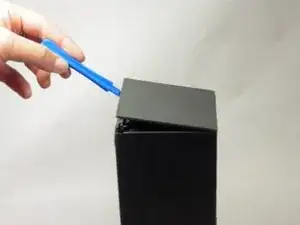
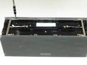
    • Remove both end caps by putting a plastic opening tool in the center of the seam. Work around the edges to pry the end caps off completely.

    • Due to interior clips holding the end caps in place, use caution when applying force.

    Can someone show the clips please in a photo?

    kenneth keen -

  2. gpR1qeYVfuiKrJPf
    gpR1qeYVfuiKrJPf
    4Xapn3AX3HIZYmBZ
    htYRDmTSEfZLbJMj
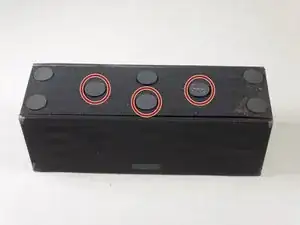
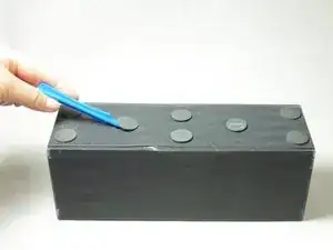
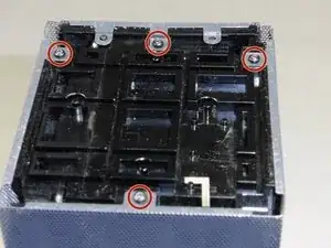
    • Turn the Jambox upside down. Peel the indicated rubber tabs off, using a plastic opening tool if necessary.

    • You may want to only take the tabs half way off to avoid re-gluing when reassembling.

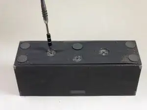
    • Remove the three T6, 7.0 mm screws under each rubber tab.

    • Because the screws are a different length, set the screws aside.

    I used rubber cement to reattach the pads. That will hold them in place and be easily removable in future.

    David Robinson -

  3. GVMKQYqV4vHagsML
    GVMKQYqV4vHagsML
    mxDNbPDkIpXGSfS5
    ZcDVcDPp2jorIIPE
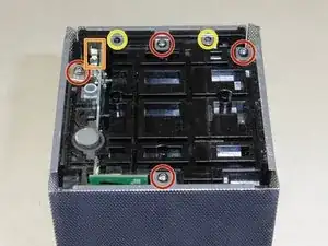
    • With the Jawbone logo facing towards you and with correct orientation, place the Jambox with the left end cap facing upward.

    • Unscrew indicated T6 9.7 mm screws.

    • Gently loosen the tabs from their anchor points so the bottom may be removed.

    • Flip the Jambox so the other end cap is facing up. The USB cable is on this side (metal grounding clip, indicated in orange). Repeat the above two steps.

  4. Sh3tMvExQQTIIqZy
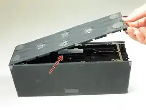
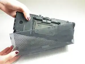
    • Pry up the bottom panel by lifting from the device.

    • Pull the bottom up. This may take a bit of force as the bottom is glued to device.

    • Once removed, the battery will now be visible.

    No glue on mine. Only two clips on each side (that you can see clearly in step 3 picture).

    Do not use force or you will break those clips.

    Jay -

  5. 4eLBA2VEVUdE31sC
    4eLBA2VEVUdE31sC
    ZpLHTRAIClrqjMfQ
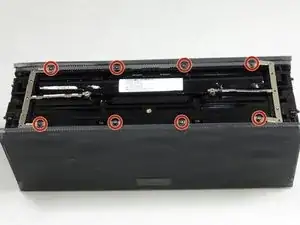
    • Before unscrewing, take a picture of the top view. That way, when you're reassembling the device, you'll know the orientation of the metal grounding plates.

    • Unscrew the eight indicated T6 9.8 mm screws. Remove metal grounding plates.

  6. mE1t61rJL3kgyFPA
    • Once all eight screws are removed, pry the sides of the Jambox to lift the body from it's shell.

  7. SvF3JIkTNocSEpQL
    • With the battery facing forward, remove the three indicated T6 9.5 mm screws.

    • Once the screws are removed, lift up the small plastic plate, revealing the auxiliary board underneath.

  8. PGa41VsT4SN1XqpS
    PGa41VsT4SN1XqpS
    Dw3QF6JQRqedKWgj
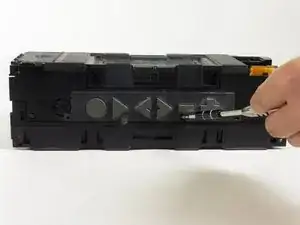
    • Turn the Jambox so that the button panel is visible.

    • Remove the indicated screws, T6 9.6 mm.

    • There is a small plastic flap obscuring the view of one of the screws, indicated in orange. In order to unscrew it, simply lift the flap out of the way.

  9. puUTogBVLEhLLaYw
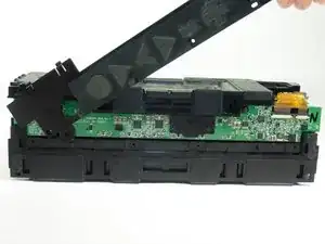
    • Pop off the button panel.

  10. g3Vb6nOcTu5IFtRu
    g3Vb6nOcTu5IFtRu
    fYPwNGNpqQlqyUSl
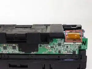
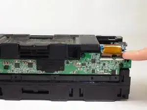
    • Remove the colored ribbon that connects the green button circuit board to the blue auxiliary board by using your finger to lift the small black tabs that clamp down the ribbon.

    Thesmallblacktabsshouldnotbelifted.Theywillbebrokenbyliftingthem.Insteadyoushouldslidetheminthedirectionoftheribbon-paralleltotheboard.Theybreakeasilyandleaveyourdeviceworthlessifnotinstalledproperly.Nowmyspacekeynolongerworks.

    kenneth keen -

    This destroyed my fix. DO NOT TRY TO LIFT THE PLASTIC TABS!!! Despite what the instruction says it is impossible to do and will break with the slightest pressure upwards. I should’ve read the comment before from another user to slide the tabs OUT in the direction of the ribbon. I’ll keep going thru the steps to finish but this might prove worthless now.

    IFIXIT needs to edit this!

    Ivan Michel -

  11. tABulXYh2gnoN6H3
    tABulXYh2gnoN6H3
    bVdCRZvUSQiMNgDL
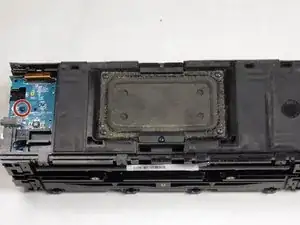
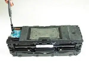
    • Remove the indicated T6 7.4 mm screw holding the auxiliary board in place.

    • Carefully lift the auxiliary board up and off to the side.

  12. jSo6dmgQj21FHaxW
    jSo6dmgQj21FHaxW
    SCHQUyFYO5EYYBem
    bdTLafA1BRuwvwJJ
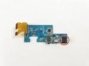
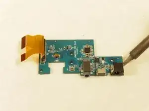
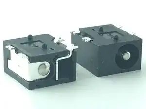
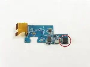
    • With the auxiliary board removed, use a soldering iron to heat the metal keeping the charge port (indicated on image) intact.

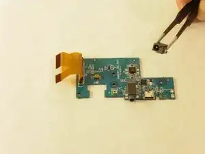
    • Remove the charge port from the auxiliary board.

    • Exercise caution when handling the soldering iron due to extreme heat.

    Where can I buy this part?

    bagi932 -

  13. uQhyYUVVpJk1Grw5
    uQhyYUVVpJk1Grw5
    2THxMKmH612SgoIM
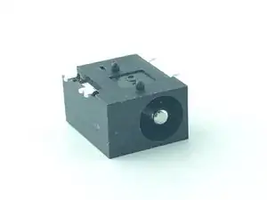
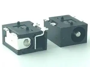
    • The new charge port will need to be soldered to the logic board. For an exact match use Digi-Key part number CP-018HPJCT-ND

    Surely there could be a direct LINK to buy this part?

    Digi-Key part number CP-018HPJCT-ND

    kenneth keen -

    Where can I buy such a port

    bagi932 -

  14. XwmHYlVrjJjkHOsC
    XwmHYlVrjJjkHOsC
    nlGYjYMWNPnFOOrY
    • With a multimeter, test all 3 PCB contacts to determine which are positive, negative and ground. Similarly, ascertain each terminal of your "new" charger port and its corresponding PCB contact. Your "new" port can be a brand-new, identical replacement or a salvaged one of approximate size, post thickness and terminal orientation.

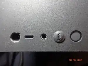
    • Unless an identical part replacement, you may have to bend your ports terminals in order to make proper contact and'or enlarge the panel opening for the AC plug as I did. To avoid repeat part failure, I hot-glued my charger port onto my PCB after reinforcing my port's terminals with thicker wire and generous solder.

Abschluss

To reassemble your device, follow these instructions in reverse order.

Gabriella Graham

Mitglied seit: 02/04/15

1118 Reputation

11 Kommentare

Skip steps 8, 9 and 10 by simply releasing the ribbon cable from the Power PCB side instead of the Button PCB side. WORKS!

Seth Link -

how can i know the auxilar bord's code?

molioze79 -

Good instruction!

Problem is that the C14 got snapped off too! Not sure if it is really needed. Possible to get the complete board?

Fred -

I lost C14 as well, anyone have a good replacement number for that?

Jason -

FYI the device will charge and power on without this capacitor. Not sure if it is needed for USB or 3.5mm output, but I don't really care about either of those scenarios.

Jason -
Just did this today. Worked like a champ. Put a little superglue gel under the new charge port and a good amount of solder. Great instructions and was an easy repair.

Drew Whitney -

I have a poblem I need the the full port board (piece) for Jawbone Big Jambox Charge , Any idea who can sell me one?

giovanni -

Mine only works on the charger... does this mean I need to replace the charge port or is it something else wrong ??? I need help please

Frances Taylor -

Excellent tutorial, just did this repair, very helpful. Didn't need to replace any parts just soldered the charger port back onto the circuitboard...

Marcel -

Excellent repair instructions! Very poor design considering the force the connector sees when connecting the AC. Glad I bought 2 extra ports because I am pretty sure I will be replacing it again in the future.

Tbone -

How can I determine if it is the charge port or the battery that needs to be replaced before I purchase parts??!!

shayne1542 -