Einleitung

If you are having trouble either connecting your Jambox via the Micro USB port or your Micro USB port has become damaged at some point, then this guide will walk you through the step-by-step process to replace it. The Micro USB port is connected with the auxiliary board, which will need to be replaced as well. This guide requires minimal soldering.

  1. FbdZmkEPUobQUF52
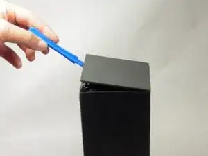
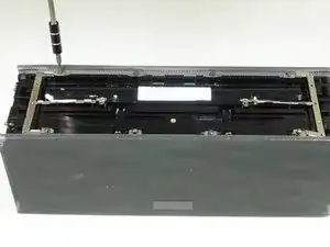
    • Remove both end caps by putting a plastic opening tool in the center of the seam. Work around the edges to pry the end caps off completely.

    • Due to interior clips holding the end caps in place, use caution when applying force.

    Can someone show the clips please in a photo?

    kenneth keen -

  2. gpR1qeYVfuiKrJPf
    gpR1qeYVfuiKrJPf
    4Xapn3AX3HIZYmBZ
    htYRDmTSEfZLbJMj
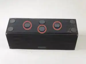
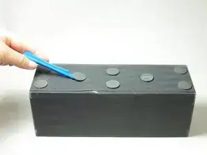
    • Turn the Jambox upside down. Peel the indicated rubber tabs off, using a plastic opening tool if necessary.

    • You may want to only take the tabs half way off to avoid re-gluing when reassembling.

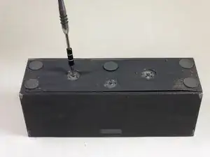
    • Remove the three T6, 7.0 mm screws under each rubber tab.

    • Because the screws are a different length, set the screws aside.

    I used rubber cement to reattach the pads. That will hold them in place and be easily removable in future.

    David Robinson -

  3. GVMKQYqV4vHagsML
    GVMKQYqV4vHagsML
    mxDNbPDkIpXGSfS5
    ZcDVcDPp2jorIIPE
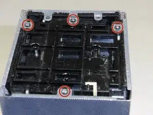
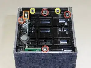
    • With the Jawbone logo facing towards you and with correct orientation, place the Jambox with the left end cap facing upward.

    • Unscrew indicated T6 9.7 mm screws.

    • Gently loosen the tabs from their anchor points so the bottom may be removed.

    • Flip the Jambox so the other end cap is facing up. The USB cable is on this side (metal grounding clip, indicated in orange). Repeat the above two steps.

  4. Sh3tMvExQQTIIqZy
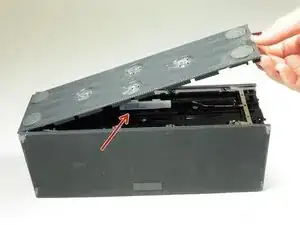
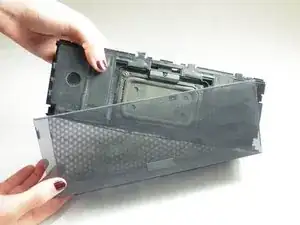
    • Pry up the bottom panel by lifting from the device.

    • Pull the bottom up. This may take a bit of force as the bottom is glued to device.

    • Once removed, the battery will now be visible.

    No glue on mine. Only two clips on each side (that you can see clearly in step 3 picture).

    Do not use force or you will break those clips.

    Jay -

  5. 4eLBA2VEVUdE31sC
    4eLBA2VEVUdE31sC
    ZpLHTRAIClrqjMfQ
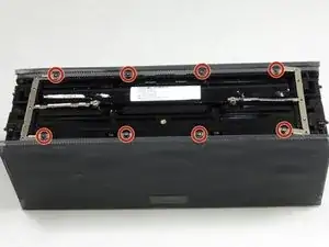
    • Before unscrewing, take a picture of the top view. That way, when you're reassembling the device, you'll know the orientation of the metal grounding plates.

    • Unscrew the eight indicated T6 9.8 mm screws. Remove metal grounding plates.

  6. mE1t61rJL3kgyFPA
    • Once all eight screws are removed, pry the sides of the Jambox to lift the body from it's shell.

  7. SvF3JIkTNocSEpQL
    • With the battery facing forward, remove the three indicated T6 9.5 mm screws.

    • Once the screws are removed, lift up the small plastic plate, revealing the auxiliary board underneath.

  8. PGa41VsT4SN1XqpS
    PGa41VsT4SN1XqpS
    Dw3QF6JQRqedKWgj
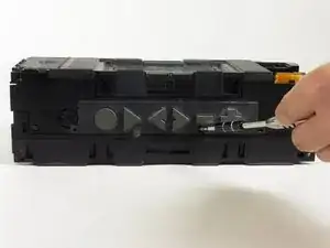
    • Turn the Jambox so that the button panel is visible.

    • Remove the indicated screws, T6 9.6 mm.

    • There is a small plastic flap obscuring the view of one of the screws, indicated in orange. In order to unscrew it, simply lift the flap out of the way.

  9. puUTogBVLEhLLaYw
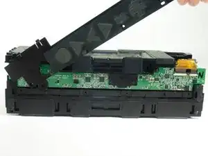
    • Pop off the button panel.

  10. g3Vb6nOcTu5IFtRu
    g3Vb6nOcTu5IFtRu
    fYPwNGNpqQlqyUSl
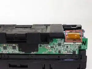
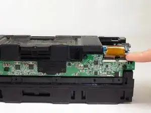
    • Remove the colored ribbon that connects the green button circuit board to the blue auxiliary board by using your finger to lift the small black tabs that clamp down the ribbon.

    Thesmallblacktabsshouldnotbelifted.Theywillbebrokenbyliftingthem.Insteadyoushouldslidetheminthedirectionoftheribbon-paralleltotheboard.Theybreakeasilyandleaveyourdeviceworthlessifnotinstalledproperly.Nowmyspacekeynolongerworks.

    kenneth keen -

    This destroyed my fix. DO NOT TRY TO LIFT THE PLASTIC TABS!!! Despite what the instruction says it is impossible to do and will break with the slightest pressure upwards. I should’ve read the comment before from another user to slide the tabs OUT in the direction of the ribbon. I’ll keep going thru the steps to finish but this might prove worthless now.

    IFIXIT needs to edit this!

    Ivan Michel -

  11. cjKWruAqSeax1cWQ
    cjKWruAqSeax1cWQ
    yBGmsCpesOMhBvP1
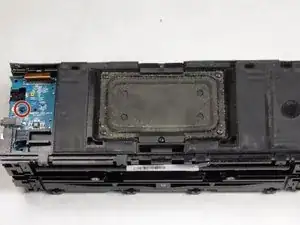
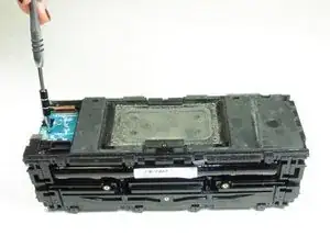
    • Remove the indicated T6 7.4 mm screw holding the auxiliary board in place.

    • Carefully lift the auxiliary board up and off to the side.

  12. mVKGPT2q2nTwqpD2
    mVKGPT2q2nTwqpD2
    bksPmPc1lXbMlPGL
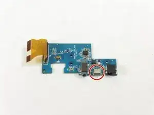
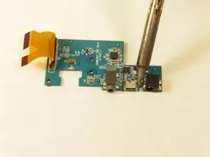
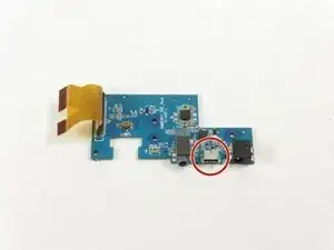
    • With the auxiliary board removed, use a soldering iron to heat the metal attaching the Micro USB port (indicated on the image).

    • Remove the Micro USB port.

    • Exercise caution when handling the soldering iron due to extreme heat.

    will this board also work with the classic jawbone?

    Kevin Kramer -

Abschluss

To reassemble your device, follow these instructions in reverse order.

Gabriella Graham

Mitglied seit: 02/04/15

1118 Reputation

7 Kommentare

Hi, great guide. My jambox has a broken headphone input. Where can I buy one to solder in. Or can I buy an entire new aux board?

conrad lucero -

I'm also looking for a new headphone input. Where do I find one?

C Dare -

You guys keep failing to mention where to get replacement parts. Any ideas??

Dave Bornack -

Where do I purchase the replacement auxiliary port?
Patrick egan -

Where do I purchase the replacement auxiliary port

Patrick egan -

Exactly the the part is missing..where do i get another?

Ijeoma Iheukwumere -

So... does this mean I am supposed to solder the port back on? Is it attaching to the board? What is holding it on? The video shows using a paste, what is the best way to reattach it?

Erin Decker -