Einleitung

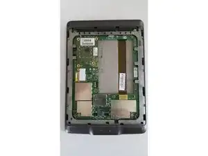
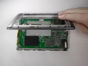
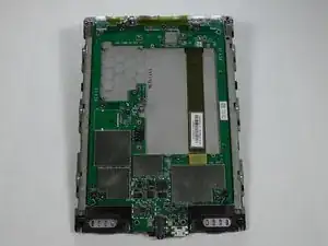
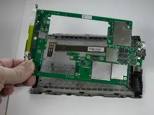
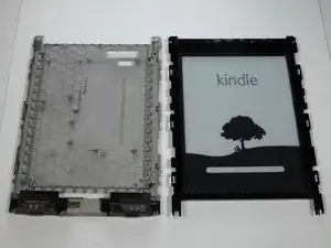
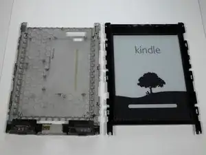
Use this guide to separate the screen from the screen support unit.

  1. HTnRmaKcPUqhJN2S
    HTnRmaKcPUqhJN2S
    PASaJ33EXJWRCpwQ
    SV4hXsVNZqyy1LNG
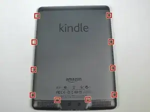
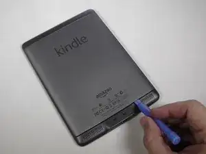
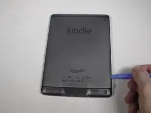
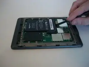
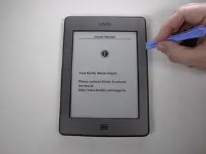
    • Use the plastic opening tool to undo the ten plastic clips around the back panel of the Kindle.

    Wear work gloves as the tool can easily slip and stab you in the hand.

    BRUCE -

  2. 3Ad5BKbISCIUnD3P
    3Ad5BKbISCIUnD3P
    KgMp3ZxIO3rjZrsK
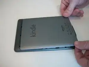
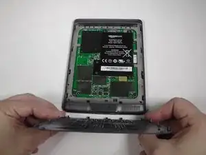
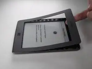
    • Gently lift the bottom and slide the panel off.

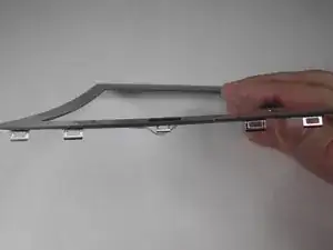
    There are four tabs on each side.The two nearest the top are open at the top, hence they slide out (back towards the power connector end.

    This is important in the reassembly stage:

    1. Align the back cover about 0.75 cm away from the top

    2. Hold the top half of the cover flat against the unit, and flex the cover away from the case a little at the bottom

    3. Slide the top and the first two clips parallel to the case

    4. snap the remaining bottom clips in place

    John Haywood -

  3. AekhLDwNenFqZHDE
    AekhLDwNenFqZHDE
    BkLQYEor6bRPyiIB
    tkvGp5mMiCQOaU1I
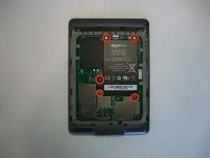
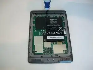
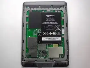
    • Use a Phillips #00 screwdriver to remove the five screws.

  4. X4tY65W6kjyWVNmc
    X4tY65W6kjyWVNmc
    VoEHW6iSUJSUA2Ym
    pNPxayDDIyXIpFcP
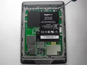
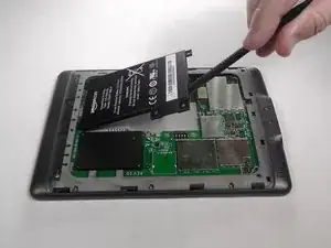
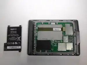
    • Using the flat end of your spudger, gently pry the battery up and remove it.

  5. ShyMEgEGfXmDiPbP
    ShyMEgEGfXmDiPbP
    qROJIeWa1sJSMylC
    efZydWv4D2WET4Z1
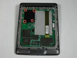
    • Remove the indicated four 2 mm screws with a Phillips #00 screwdriver. (Units with the 3G assembly have Phillips #000 screws.)

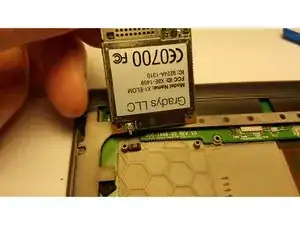
    • Next, gently lift the 3G assembly with a Spudger or your fingers.

    • This Kindle Touch is the WiFi only model and comes with a plastic placeholder instead of the 3G assembly.

    • Disconnect the antenna lead by carefully prying it off the 3G board with a plastic tool.

    The 3G model has an antenna connector near the top left on the underside.

    Chad Wade Day, Jr. -

  6. sifHtIpPRQDTJCkG
    sifHtIpPRQDTJCkG
    DrwZj6EDLSHuKA6H
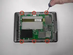
    • Using a Phillips #00 screwdriver, remove the six 4 mm screws to access the front plate.

  7. BfjiOtVTeJi6XNJL
    BfjiOtVTeJi6XNJL
    ytdMLIEIESvLUEXS
    YdXvOU3nSXLmEjkJ
    • Use the plastic opening tool to pry the bezel from the top and sides

    • The bottom of the bezel will be glued, so be careful when sliding the clips out.

    • The clips can be easily bent, so do not try to force them out. If you do bend some, they can be bent back.

  8. 6pQW4DOyAvkPMbpO
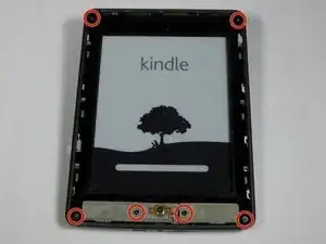
    • Use your Phillips #00 srewdriver to remove the indicated screws.

    • There are three pairs of screws that are each different. The screws on the top corners are 4 mm #00 Phillips screws, the screws on the bottom corners are 2 mm #00 Phillips screws, and the black bottom center screws are 6 mm #00 Phillips screws.

  9. JB4bg5IHkrfCRtgm
    JB4bg5IHkrfCRtgm
    Y2PKsxyJhOtmBAty
    • With the screws removed, gently remove the case from the internals.

  10. PUriUU6SIxqbZ3Tc
    PUriUU6SIxqbZ3Tc
    goPuLfxU3aCTIUoi
    IZNdEYs1pSLgJuot
    • With the screen facing you, use your heated iOpener or other heating element to loosen the glue holding the WiFi unit to the screen. After 30 seconds, remove the heating element.

    • After the glue is loosened, use a thin tool, like a Spudger or small plastic opening tool, to separate the WiFi unit from the screen.

  11. P2SZExxOBWWnlFsF
    P2SZExxOBWWnlFsF
    5VFu4sBNeLByZvvR
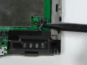
    • With the motherboard facing you, use the pointy end of your Spudger to gently separate the two speaker's connectors.

    • This connector type requires being lifted out of place, not pulled. Accidentally pulling may damage the wires.

    • During reassembly, make sure the speaker's connectors are not pushed behind the motherboard.

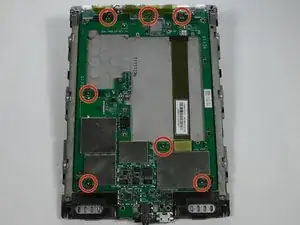
    • Use your #00 Phillips Screwdriver to remove the seven 2 mm screws.

  12. hgIwB24gyv6lBWN4
    hgIwB24gyv6lBWN4
    hW1LNxO4RjOOXmnd
    FC4PVuUfQOhcOoNk
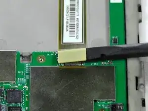
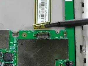
    • Use a Spudger to separate the display's connector from the motherboard.

    • Gently remove the motherboard from the display support.

  13. ZRcZRiMNvhOHSMBf
    ZRcZRiMNvhOHSMBf
    VTSMVwXOdGPLe1ni
    vUWMY5IackSTFThs
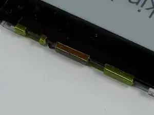
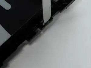
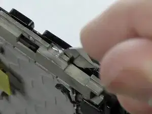
    • Using your Metal Spudger, place the pointy end into the top of the clip.

    • Gently rotate the Spudger and lift the plastic unit to create a gap on the side.

  14. NSXwRsVGBdMmI2Gu
    NSXwRsVGBdMmI2Gu
    5EsmQTXx3IQSbE1O
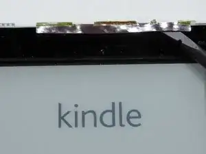
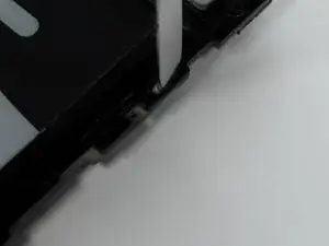
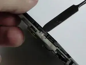
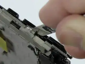
    • Use the Spudger in the gap to pry the clip open.

    • Repeat for the other clips.

  15. BvjyymyqAe66Tcm3
    BvjyymyqAe66Tcm3
    yhkhYvTR5LAUZtfx
    ieCxNIy1wYsovZMS
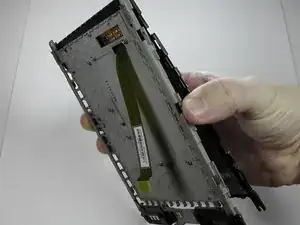
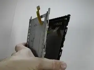
    • With the clips separated, gently guide the Screen's Motherboard Connector through the hole.

Abschluss

To reassemble your device, follow these instructions in reverse order.

Adam Yerly

Mitglied seit: 20/01/15

1885 Reputation

6 Kommentare

I would love to know where I can get the replacement screen. Any links?

Ryan Lee -

Good guide, thanks, finally, if you need to remove the screen itself from the black plastic frame you can do this inserting the spudger carefully between the screen and the black plastic frame and gradually moving it all round the frame. It will help if you put a heated silicon gel pack over each side before trying to release it

John Chapple -

I have a Kindle with half of screen responding to touch

Is the touch incliduded on the screen itself? Will replacing the screen help or is there another way to fix the touch?

Mohd. Nauman Khalid -

No, the touch circuitry is built into the motherboard.
Chris Halliwell -

Where do you buy the screen replacement part for the Kindle Touch?

Andrew Manger -

I got one on ebay for about $15.
LoriP408 -