Einleitung

  1. MgoBGV6CKSFRga1A
    MgoBGV6CKSFRga1A
    UTKW6uPEJAukoSsU
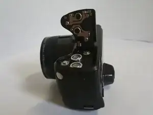
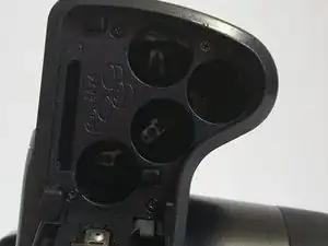
    • Open the battery cover and remove batteries from the camera if any are inserted.

  2. NeUObAIPpb2QVp62
    NeUObAIPpb2QVp62
    GeFdnpjVCUTOGQNU
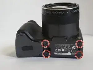
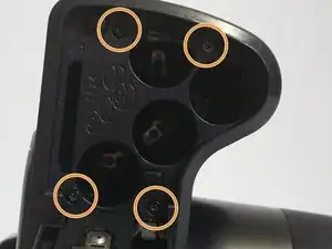
    • Use a 00 Phillips-Head screwdriver to remove screws:

    • Remove the 3 mm screws from the camera

    • Four (4) screws are in the bottom of the device

    • Four (4) screws are inside the battery cover

  3. FsE1DeEBFFaQvQT6
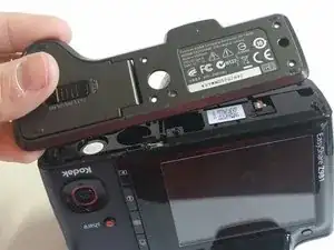
    • Start from a corner and gently remove the cover.

    • The cover will easily lift off, so not much pressure is required.

    • Make sure to gently remove the bottom cover in order to avoid breaking the plastic.

  4. eKminhGGmZxorAYB
    eKminhGGmZxorAYB
    HgGScZoF4uxkWkPV
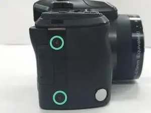
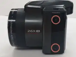
    • Use a Kreuzschlitzschraubendreher #00 to remove the 4 mm screws from each side of the back cover of the camera.

    • Two (2) screws are located in the left side of the device

    • Two (2) screws are locatecd in the right side of the device

  5. XDh3VYtGOlodkICa
    XDh3VYtGOlodkICa
    Z1REvnQhZbdWpSmQ
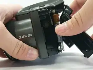
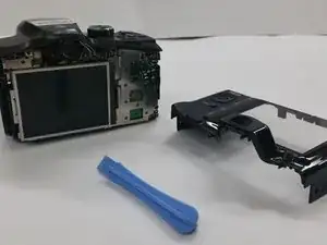
    • Insert the Plastic Opening Tool in to the crevices of back cover and gently apply pressure

    • Be gentle while removing the cover, to avoid cracking the case

  6. xrATnLEAGGrhbJIQ
    xrATnLEAGGrhbJIQ
    QqEAFnqh3nWJvJKK
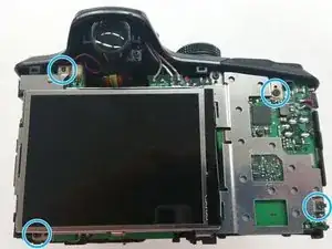
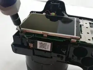
    • Once the back cover is removed locate the four 3mm screws holding the screen and the metal brace to the circuit board

  7. 1bMyBYQMOfgCxgtA
    1bMyBYQMOfgCxgtA
    l6WM5fVdaAbAcuJq
    2ZtnOAfTJ4y4aXIc
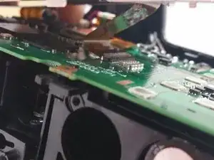
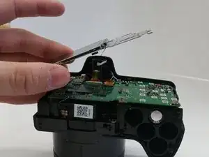
    • Gently lift up the metal brace and use a pair to disconnect the ribbon cable connecter

    • Use Tweezers to disconnect the ribbon cable connector.

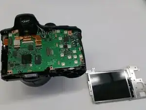
    • Once disconnected remove the screen brace from the circuit board

    • Use extreme caution when removing the LCD brace pulling the brace may tear the cable

Abschluss

To reassemble your device, follow these instructions in reverse order.

Daniel Ramirez

Mitglied seit: 03/03/15

152 Reputation

0 Kommentare