Einleitung

  1. Y2hBsWeEIdhoXJNo
    Y2hBsWeEIdhoXJNo
    6tRZU6Y4X5rWkpKq
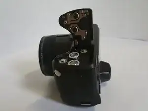
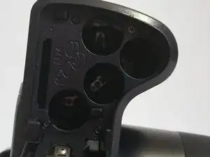
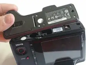
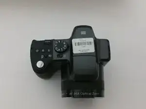
    • Open the battery cover and remove the AA batteries from the camera if any are inserted.

  2. NdiwqF3ilCaRAQLO
    NdiwqF3ilCaRAQLO
    1qaI6ophmUR2nHh4
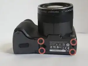
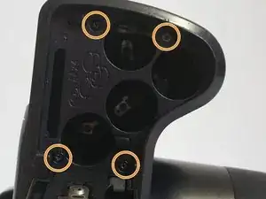
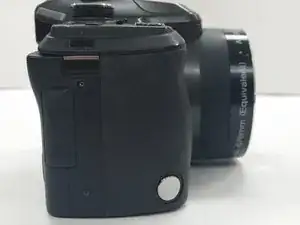
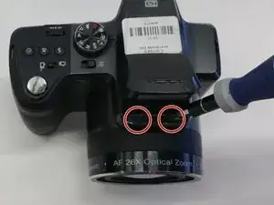
    • Remove all screws on the outside of the camera with a 00 Phillips-Head screwdriver

    • Eight (8) 3mm screws on the lower portion of the camera

    • Four (4) screws on the bottom of the camera

    • Four (4) screws inside the battery cover

  3. JnmsvXX3nbohrTIT
    JnmsvXX3nbohrTIT
    TLgQNCOcguH2eFlo
    KWJ5ONiTa4xpP3d3
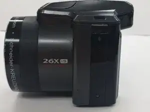
    • Detach the bottom part of the camera by removing four (4) 3mm screws

    • Two (2) screws are located in the left side of the device

    • Two (2) screws are locatecd in the right side of the device

  4. uLIcXpu4RBwEZM2y
    uLIcXpu4RBwEZM2y
    ZuedYiHwNMWQQUft
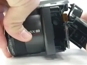
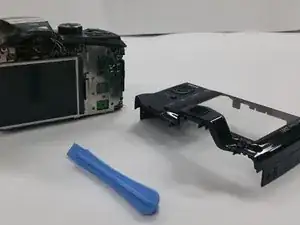
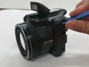
    • Use the Plastic Opening Tool to put light pressure and remove the back cover of the camera

    • Be gentle when removing the back cover

  5. yBqYVSroWjfKVaOP
    yBqYVSroWjfKVaOP
    A2KyotmmQjRlPThu
    3CRPR2xBEVlspBfk
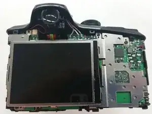
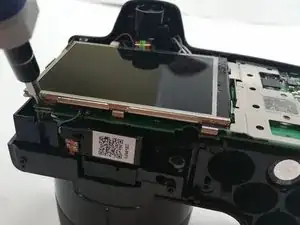
    • Unscrew the four (4) 3mm screws to remove the screen from the circuit board

    • Use Tweezers to delicately detach the ribbon cable

    • Carefully remove the screen brace from the circuit board

  6. pRtBUhjXRuNBiFf1
    pRtBUhjXRuNBiFf1
    nnGdNreOCpUUJMOP
    aYptNcZ5w4gNSMRP
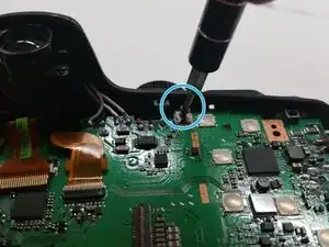
    • Remove the two (2) 3mm screws from inside flash compartment

    • Remove one (1) 3mm screw from the circuit board

  7. oTmunfhRRX5AimKA
    oTmunfhRRX5AimKA
    XVeCYtdVhIQDaldu
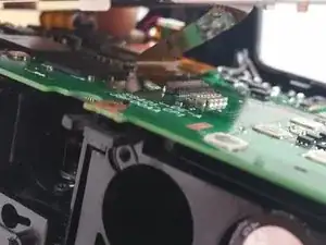
    • Use the Tweezers to detach the ribbon cable connecter from the circuit board

    • Use the Plastic Opening Tool to gently apply pressure on the top of the camera and remove the upper portion

  8. rBVgwp1QRdBvFjmr
    rBVgwp1QRdBvFjmr
    KLxof1F5XnhAGnAk
    tgq4RT5ZnOZemgqt
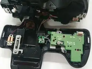
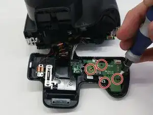
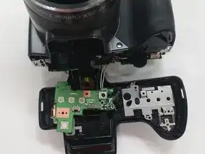
    • Remove the four (4) 3mm screws from the circuit board directly underneath the shutter button and gently move the circuit board aside

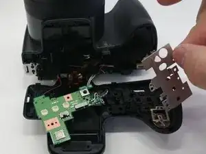
    • Lift up the metal clamp

    • Use caution when removing the circuit board to avoid tearing the wires connected

  9. YvC2kfuuDVNDfXaQ
    YvC2kfuuDVNDfXaQ
    YNsKGXTVtySQYGVR
    BlmPwJWh54aMU2Q3
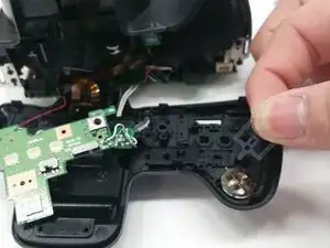
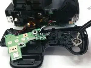
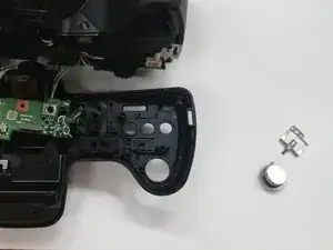
    • Pull the small brace on top of the shutter button

    • Using the Tweezers, gently remove the shutter button

Abschluss

To reassemble your device, follow these instructions in reverse order.

Matthew Myers

Mitglied seit: 03/03/15

217 Reputation

Ein Kommentar

looking for z981 bottom wrist grip jwkcm1978@hotmail.com
jwkcm1978 -