Einleitung

In this guide, you will learn how to repair and replace a faulty Mode Dial for your Kodak PixPro AZ251. This may be necessary if the camera mode does not change upon turning the Mode Dial, or if the Mode Dial is loose.

  1. W1kmoSo2CFRauKtg
    W1kmoSo2CFRauKtg
    HSvixSUSNWUock6e
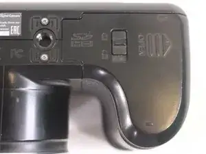
    • Slide switch to open lock position.

  2. MWlabhKwFUPtDoEA
    MWlabhKwFUPtDoEA
    rTWSxQPCXfXgwwff
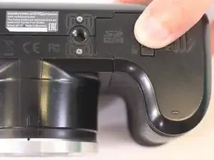
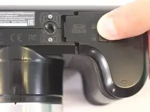
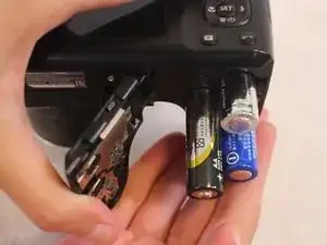
    • Press down on the battery cover and slide outwards to open.

  3. oVkvnSZvtkesDqdt
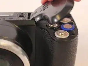
    • Remove the batteries.

  4. GlcE4UsnZyRuXdU3
    GlcE4UsnZyRuXdU3
    GUQ53eVAviPEdtNj
    Ho6TUfiMovbuCtvB
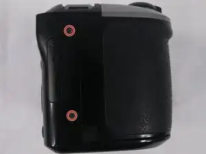
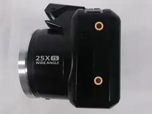
    • Remove a total of four 5mm JIS #000 screws from around the camera:

    • Two screws from the right side.

    • Two screws from the left side.

  5. HJUVNCaNevmXROPY
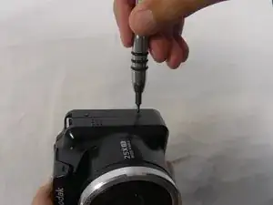
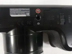
    • Remove the single 5mm Phillips #00 screw from the bottom.

  6. 52kBqpvLjhsdwGUw
    52kBqpvLjhsdwGUw
    V5EAt3iVMF4ATGFJ
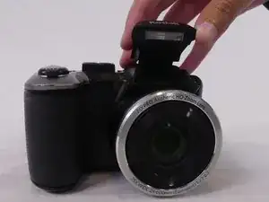
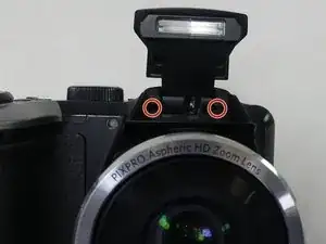
    • Open the flash module.

    • Remove the two 6mm JIS #00 screws found inside of the flash housing.

  7. HJjJfq3gYsSLa4ZL
    HJjJfq3gYsSLa4ZL
    MGK5fc6rkGkFR1GK
    GYqvRJMnX1OHalFF
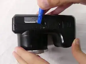
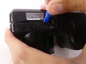
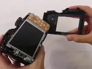
    • Use a plastic opening tool to pry apart both halves of the camera.

    • Remove the back panel.

  8. xfZYyemH44ZbsOXm
    xfZYyemH44ZbsOXm
    i4Us4wbBjD4FhErR
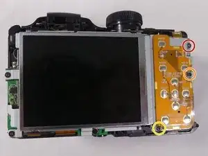
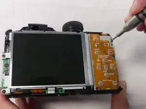
    • Remove these three JIS #000 screws from the control board:

    • 5mm screw.

    • 4mm screw.

    • 2mm screw.

  9. RYXP2P4Li3BMIEaj
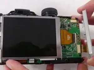
    • Pull the small metal switch plate to the side.

  10. a2uWfVqkZZC3iwm4
    a2uWfVqkZZC3iwm4
    DEpKf1mkXSH3uXK3
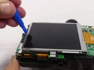
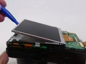
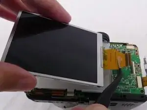
    • Pry the LCD screen out of the metal housing plate with a plastic opening tool.

  11. hSrSqIV3vrfciYG5
    hSrSqIV3vrfciYG5
    cTPu1sE5fRpAxvqR
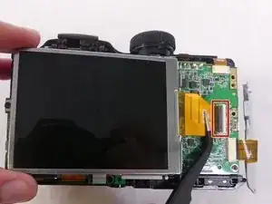
    • Use a spudger to flip up the retaining flap on the display ribbon cable ZIF socket.

    • Pull the orange cable out of the socket.

    Where do you buy a new screen from

    lewis taylor -

    Where can I buy the screen from as I can’t find the screen for the camera or can I buy a different lcd screen

    lewis taylor -

  12. YTQMMTAuEs2ND1jV
    YTQMMTAuEs2ND1jV
    5CKGNWekvYbXBakP
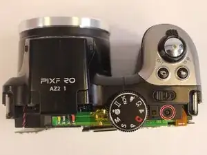
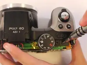
    • Remove one 4-mm screw using a J000 screwdriver from the top of the camera, near the mode dial.

  13. KnERoY6M3beEWmaO
    KnERoY6M3beEWmaO
    ZbhXfLsHWRbV6SIF
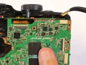
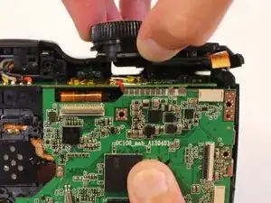
    • Using the tweezers, disconnect the orange cable connection at the top of the motherboard near the mode dial.

  14. A5ChOZqGb1lIXTgF
    A5ChOZqGb1lIXTgF
    bYPJcCVJKsc5NOjE
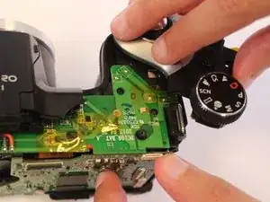
    • Pull the top side cover up.

    • Rotate the top side cover to the right.

    • Rotate carefully to avoid breaking the screw attaching the top side cover to the main body of the camera.

  15. Pdpx2GoBTl4BGfBa
    Pdpx2GoBTl4BGfBa
    lLGLyI6mExwqXedZ
    • Turn the camera upside down.

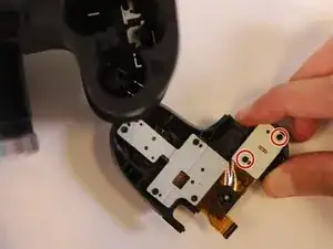
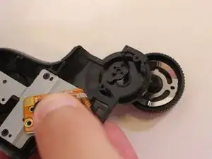
    • Remove two 2mm JIS #000 screws from the metal base of the mode dial.

  16. 5XgRdTctAjlyiDYO
    5XgRdTctAjlyiDYO
    Enb6DAcVK2E2qnef
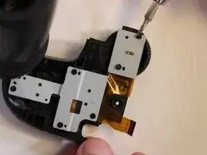
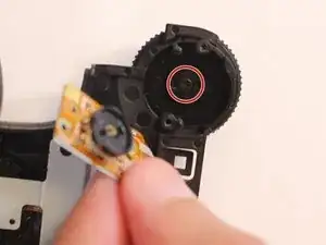
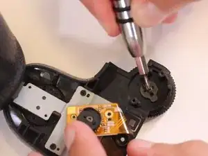
    • Lift the metal base and remove the 4mm JIS #000 screw from the center of the mode dial.

  17. iufDdw2Bj4PdKSXQ
    iufDdw2Bj4PdKSXQ
    jxbKG4Qx6lVaeHF1
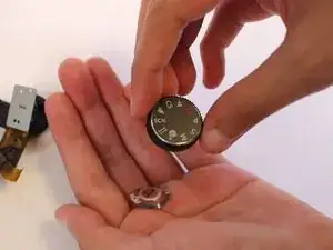
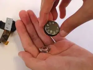
    • The mode dial should now be loose and can be easily removed from the top side cover.

    • Turn the mode dial upside down to remove the metal part inside.

Abschluss

To reassemble your device, follow these instructions in reverse order.
Rachel Llewellyn

Mitglied seit: 23/02/18

509 Reputation

0 Kommentare