Einleitung
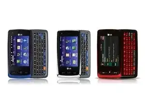
To start you are going to want to know some things:
An ESD Safe mat is recommended, but optional. This also includes the ESD safe bags, and Kapton tape.
REQUIRED: Spudger or some kind of tool to separate pieces and Phillips #00 Driver
This phone has several main components in the following order:
- Back Plate
- Battery
- Rear Chassis
- Speaker Housing
- Main Board
- Keyboard Bezel
- Button Pad
- Slider Plate
- Call / End / Clear buttons and board
- LCD
- Touch Screen / Top Plate
Keep in mind that this is in fact a phone that is held together by snap in plastic pieces. If you pry things too roughly or force things to open too quickly you can damage the device.
These steps should cover most if not all details of the take apart and re assembly.
Werkzeuge
-
-
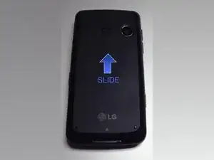
Remove Back Plate by sliding toward the top of the phone
-
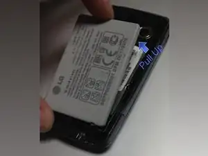
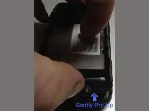
Remove battery by using a fingernail, Spudger or plastic card to pry upwards in battery pry area.
-
-
-
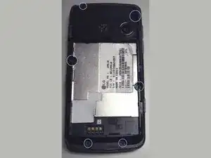
Remove PH #00 screws from indicated areas. There are 6 total screws of equal size.
-
Use spudger or fingers to carefully pry the Rear Chassis from the phone. I suggest opening the charge port door and prying from there. Once you get a start, work around the edges slowly.
-
-
-
Cleaning / Removing the Speaker:
-
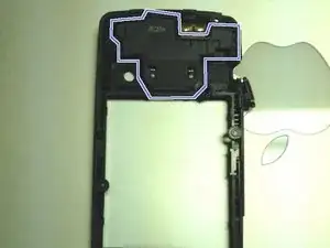
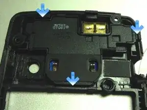
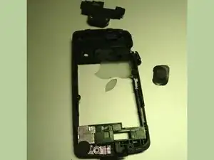
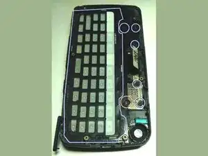
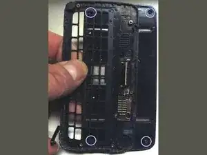
After removing the rear chassis you will see a box at the top of the phone. (Image 1) Remove this by using a spudger to pry the clips on the outside of the chassis away from the speaker housing. Once the top and right clips are loosened you can pry the housing out from the bottom.
-
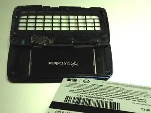
In image 3 I have removed the mesh from the chassis. This allows me to use canned air or alcohol to clean the speaker holes. Let it dry and replace the mesh cover. The housing should snap back in when inserted top of case to bottom.
-
-
-
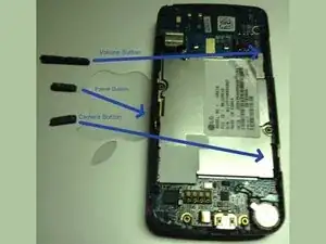
Remove buttons from outer edges as indicated.
-
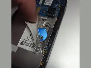
Carefully peel back the label shown. Remove two PH #00 screws from cover. Keep these screws separate as they are different from the Rear Chassis screws.
-
-
-
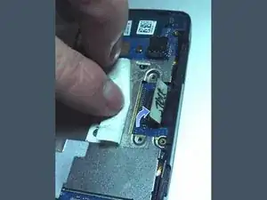
Use spudger to pop off the connector.
-
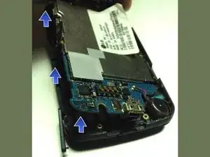
Gently use spudger or fingers to pry up main board. Try multiple areas around the board. In my case the left side was easier to pry. It should come up fairly easy.
-
Once the board is removed I recommend storing it in an ESD safe bag seen in the tools section. If you do not have ESD bags available you can use the rear chassis and the back plate to hold it.
-
-
-
Remove the keyboard buttons and the six screws that hold the keyboard bezel to the sliders. These screws should all be the same size and color of the rear chassis.
-
Once bezel is removed use the spudger to pry the cable from the bezel.Then feed it through the gap. I have stripped one of my screws. This causes me to be unable to remove the keyboard bezel.
-
4 screws on the slider plate will be covered with black adhesive covers. Scrape these off and save them for re-use if possible. The screws are the same as the rear bezel and slider bezel screws.
-
If you have stripped the screws like me, you can take the first two out while slid open. The second two are accessible if you open the slide half way and push it slightly up or down to expose screws.
-
-
-
Remove the slider plate. This can be done by inserting a plastic card or thin pry tool between the colored top plate and the slider plate. Once inserted carefully work the card around the edges until slider plate pops off. Note: This can be tough to open the first time
-
-
-
Removing Connectors
-
Most connectors are just simple vertical pop offs. To get them off, twist a spudger or card underneath the connector.
-
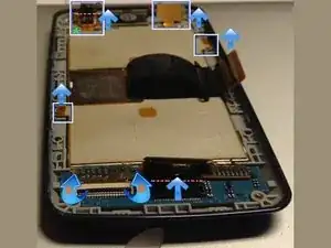
Connector "A" in green is the same, but be careful. This connector connects two cables together, instead of the cable to board connector. Make sure your tool is between the two layers and not under the bottom one.
-
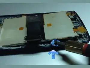
Figure "B" in orange is covered with Kapton or Mylar tape. Peel the tape off and either save it or plan on cutting a new piece. The connector is a latch. The black bar should normally lie flat. Pop it up 90 degrees to a vertical position.
-
Now use a spudger to push the connector cable toward the LCD as shown in image 2. It should slide out of the latch connector.
-
-
-
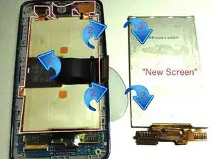
Carefully use spudger to pry out the LCD panel. This should take minimal force if done from the right spot.
-
Tools Warning: DO NOT use a flat head screwdriver if you want to keep the LCD panel. A screwdriver can damage it.
-
Replacing an LCD? You will most likely have to peel the backing off the original LCD panel. First carefully peel back the main black connector then proceed to peel the tan / silver back from the LCD.
-
Removal Note: Be careful not to rip out any connectors or apply too much pressure to them. This is also going to be VERY sticky and will want to roll into a cylinder. Even though it is sticky it may not be sticky enough to fully stick the the back of the new LCD.
-
LCD Storage: if storing the LCD, a slim plastic case with a cloth on the LCD side may be a good way to store it. This is shown in image 3.
-
-
-
Reassembly Notes: For the most part you can follow these steps backwards to work your way through. Remember to just snug the screws. Too much pressure can strip the threads or the heads. There are a few things to consider:
-
LCD Installation Tips: When putting in a new LCD, be sure that the inside of the front panel and the LCD are as lint free as possible. This would be where ESD wrist straps / mats make this easier. If you are fortunate enough to have an ionizer it would be a good time to use it.
-
LCD tan / silver backing: This may not stick properly to the back of a new LCD. Try putting it on as well as possible and quickly snapping on the slider panel.
-
LCD connectors note: Remember to replace the Kapton / Mylar tape after installing the latch connector. The tape is pictured in Step 6 Image 2 and removed on Step 7 image 1.
-
For now these are all of the reassembly tips I am giving. These guides are VERY time consuming. It took a lot of spare time just to get this one done. If there are any questions feel free to comment or contact me.
-
If there are any steps that need to be modified please say so in the comments section.
