Einleitung
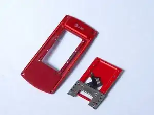
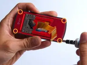
Your phone uses a spring to help make the keypad slide in and out seamlessly. It is located between the front and back case. In this guide you will learn how to remove and replace this mechanism.
Werkzeuge
-
-
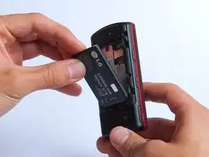
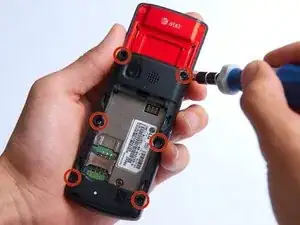
On the back of the phone, place your thumb on the three raised bumps and slide the back cover upward.
-
-
-
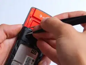
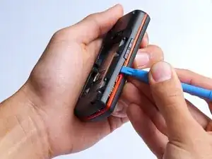
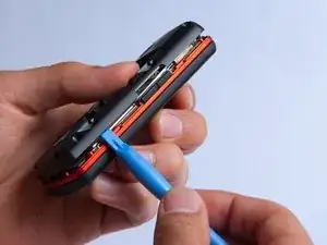
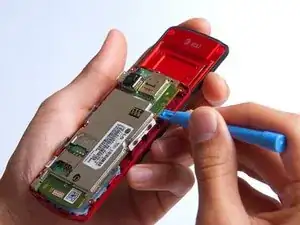
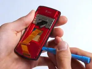
Use the plastic opening tool to pry the back cover off. Insert the tool between the back cover and red mid section and go around the entire phone.
-
-
-
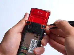
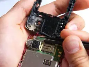
Use the tweezers to remove the red and black wires connecting the speaker to the green motherboard by pinching the sides of the plastic base near the motherboard.
-
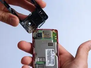
Set the back cover with the speaker aside.
-
-
-
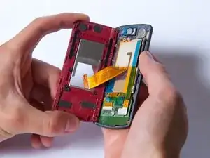
Use the plastic opening tool to gently lift the snapped-in motherboard from the front panel.
-
-
-
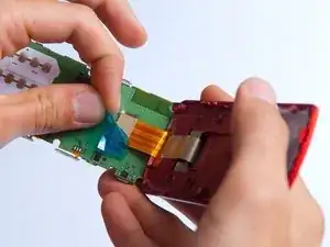
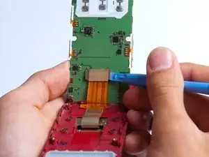
With the plastic opening tool, gently pry the LCD connector from the motherboard.
-
Set the motherboard aside.
-
-
-
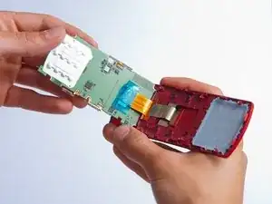
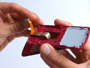
Gently pull the orange ribbon from the number pad casing.
-
Set the number pad case to the side once it is detached from the ribbon.
-
-
-
Pry the red sliding backing from the front cover by inserting the plastic opening tool in between the two sections and going around the entire phone.
-
Set the red sliding backing and front cover to the side.
-
-
-
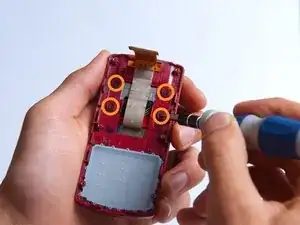
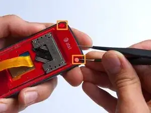
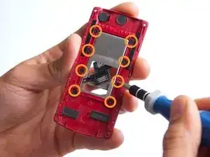
Unscrew the eight Phillips #000 (1mm) screws on the back side of where the sliding mechanism is located.
-
To reassemble your device, follow these instructions in reverse order.
