Einleitung

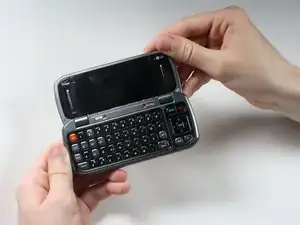
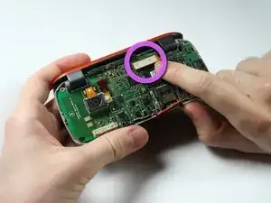
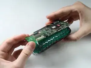
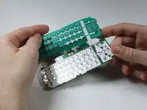
The circuit board and full key board are attached and must be installed together as one unit. Do not try to separate them.

  1. 6FPqpVgZXCQgArg3
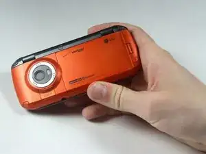
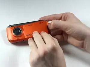
    • Place the phone so the screen side is facing down.

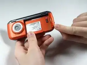
    • Locate the latch at the end of the phone, opposite of the camera.

  2. QqwUSSUSd5xGwSjR
    • Push/pull the latch away from the camera, causing the battery to pop out.

  3. VkUYE6UCGHus5KCI
    • Remove the battery.

  4. qIxK2FXeS5WPOK2s
    qIxK2FXeS5WPOK2s
    Ve6OWftkHNgHkrjH
    • Remove the 5 screw covers on the back of the phone using a Push Pin.

  5. veQYUnu2F5SZ5xvU
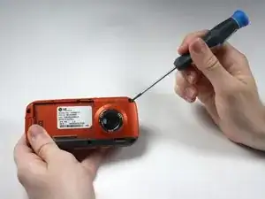
    • With a Phillips #00 Screwdriver, remove the five 3.44 mm screws that were under the screw covers.

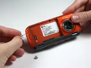
    • Also with a Phillips #00 Screwdriver, remove the screw that was revealed once the battery was removed.

  6. 5MqL3FuxaCqJ5cSK
    5MqL3FuxaCqJ5cSK
    VdPXgjvNBvRWr2KD
    • Open the phone.

  7. dYMxmN5QnMJxKwGv
    dYMxmN5QnMJxKwGv
    eV2vUKIH1fAqHcGG
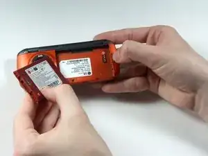
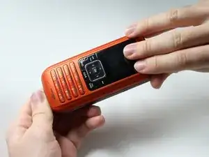
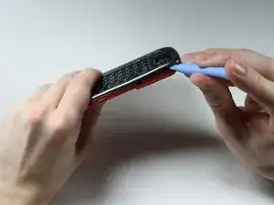
    • Starting at the card slot or charger port for greater ease, pry off the colored casing from the back of the phone using the Plastic Pry Tool (or a finger nail may work).

    • Prying open the part just to the left of the right hinge can be difficult.

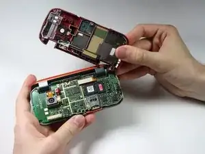
    • Remove the back colored casing and set it to the side.

  8. hTIPQCVQV3EbqUVW
    hTIPQCVQV3EbqUVW
    MisTmfZylCQOyunh
    • Gently pry and detach the connection located near the hinge with fingers.

  9. t4HqKOgNINtdhmnm
    t4HqKOgNINtdhmnm
    FTISwrHVJEXTY2AZ
    • The circuit board and the key board will be attached, as shown in the second picture.

    • Lift them both out from the rest of the phone.

    • Do not try to the detach key board pad from the circuit board. They are replaced as a unit.

Abschluss

To reassemble your device, follow these instructions in reverse order.

Stephanie Villavicencio

Mitglied seit: 06/04/12

28 Reputation

0 Kommentare