Einleitung

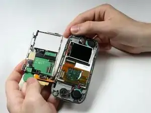
Installing the Number Keypad and the LCD Screen can be done at the same time. Note, however, that the Keypad and the hardware casing are connected and must be installed together.

  1. 6FPqpVgZXCQgArg3
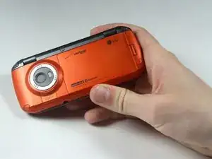
    • Place the phone so the screen side is facing down.

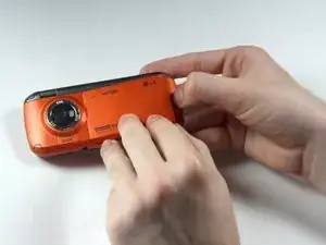
    • Locate the latch at the end of the phone, opposite of the camera.

  2. QqwUSSUSd5xGwSjR
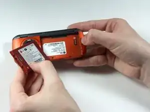
    • Push/pull the latch away from the camera, causing the battery to pop out.

  3. VkUYE6UCGHus5KCI
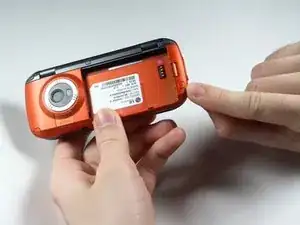
    • Remove the battery.

  4. qIxK2FXeS5WPOK2s
    qIxK2FXeS5WPOK2s
    Ve6OWftkHNgHkrjH
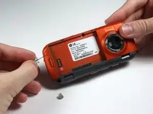
    • Remove the 5 screw covers on the back of the phone using a Push Pin.

  5. veQYUnu2F5SZ5xvU
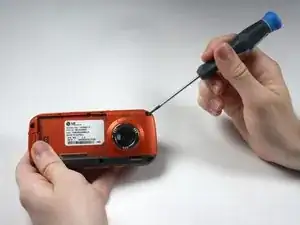
    • With a Phillips #00 Screwdriver, remove the five 3.44 mm screws that were under the screw covers.

    • Also with a Phillips #00 Screwdriver, remove the screw that was revealed once the battery was removed.

  6. 5MqL3FuxaCqJ5cSK
    5MqL3FuxaCqJ5cSK
    VdPXgjvNBvRWr2KD
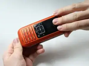
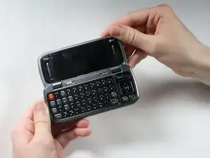
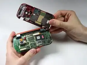
    • Open the phone.

  7. dYMxmN5QnMJxKwGv
    dYMxmN5QnMJxKwGv
    eV2vUKIH1fAqHcGG
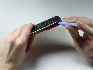
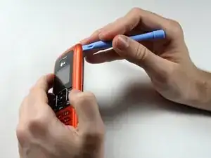
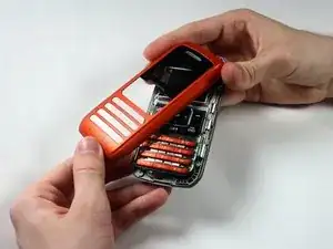
    • Starting at the card slot or charger port for greater ease, pry off the colored casing from the back of the phone using the Plastic Pry Tool (or a finger nail may work).

    • Prying open the part just to the left of the right hinge can be difficult.

    • Remove the back colored casing and set it to the side.

  8. hTIPQCVQV3EbqUVW
    hTIPQCVQV3EbqUVW
    MisTmfZylCQOyunh
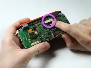
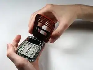
    • Gently pry and detach the connection located near the hinge with fingers.

  9. t4HqKOgNINtdhmnm
    t4HqKOgNINtdhmnm
    FTISwrHVJEXTY2AZ
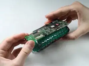
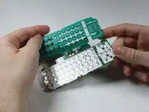
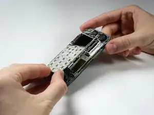
    • The circuit board and the key board will be attached, as shown in the second picture.

    • Lift them both out from the rest of the phone.

    • Do not try to the detach key board pad from the circuit board. They are replaced as a unit.

  10. OpvGtoFbkYOpLu6s
    • After removing the circuit board and key board, separate the top part with the screen from the bottom part by detaching the hinges.

  11. bZlNGTdOrlmGAYeB
    • Careful! The paint is easy to scratch.

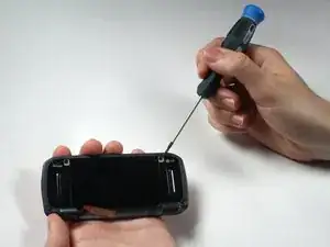
    • Remove the 4 screw covers from top piece of phone by using a Push Pin.

  12. JLSyjiWOUWygAJZ6
    • Remove the four 3.44 mm screws that were under the covers using a Phillips #00 Screwdriver.

  13. cjyNtNIVqspMeGHt
    cjyNtNIVqspMeGHt
    miuEWVrjelAZ4Gsa
    uUbUgtR16APHm1Ls
    • Be careful while breaking the adhesive connecting the speaker and the casing in the following sub step so that you do not tear any wires.

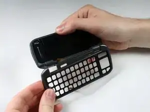
    • Pry open the colored casing using the Plastic Pry Tool.

    • Remove the number pad and place it to the side.

  14. MSIKJ1VnWJtScted
    MSIKJ1VnWJtScted
    BiFaMu2xilRiyKhc
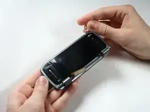
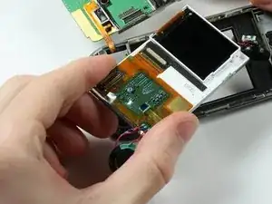
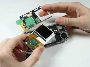
    • Because the Number Keypad is attached on one side and on top of the outer screen, open its metal casing, in a "door-opening" manner.

  15. dZccGxaQbldkxukN
    • The pieces connected by wires are magnets and are removable.

    • Remove the LCD Screen.

  16. lQc1y6hbVUETsGhF
    • The Number Keypad and its metal casing are attached to the clear plastic screen that the LCD Screen was in. Replace both the Keypad and the casing as a unit.

Abschluss

To reassemble your device, follow these instructions in reverse order.
Nathan Farnum

Mitglied seit: 05/04/12

72 Reputation

0 Kommentare