Einleitung
The LG Neon II GW370, a cell phone released in 2010, is complete with a camera, music player, and slide out QWERTY keyboard. It comes in a variety of colors, the most common being blue, green, orange, red, and black.
Werkzeuge
-
-
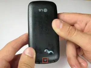
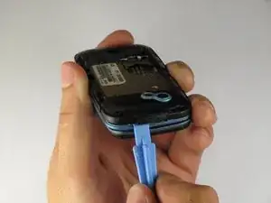
To gain access to the phone’s speaker, grip the phone firmly in an inverted position with the back of the unit facing up and the LG insignia positioned away from you.
-
Using both hands as support, use your thumbs to gently guide the rear housing away and in the direction of the arrow.
-
-
-
After removing the phone’s back-panel, securely cushion the front of the phone on a soft surface such as a cloth or your hand.
-
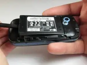
Gently insert a spudger under the lip of the battery, preferably the lip away from the camera eye.
-
Gently pry the battery out of its seated position.
-
-
-
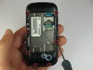
To separate the button board/circuit module from the phone main frame, firmly, but gently, unscrew (counter-clockwise) the seven outside 4 mm screws along the rear outside rim of the main body.
-
-
-
Locate the lifted portion of plastic on the bottom end of the phone near the charger.
-
Slide the plastic opening tool underneath this lip, and gently pry the black plastic cover off.
-
-
-
Loosen the two captive screws on the metal plate near the center of the phone using the Phillips #0 Screwdriver.
-
-
-
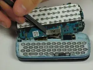
Using the plastic opening tool, gently pry the circuit board from the phone.
-
The partially separated circuit board may be attached to the main button area by factory adhesive/tape. If so, use a soft padded surface to rest the mother board on. Your work area will still be accessible without separating the two units.
-
-
-
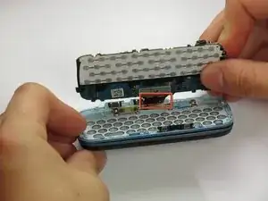
After prying the circuit board up, it will be attached by black tape. This tape connects the circuit board to a metal rectangle.
-
Use the spudger between this metal rectangle and the phone to disconnect the two halves of the phone.
-
-
-
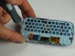
Unscrew the four 1.75 mm screws located on both sides of the black tape using a Phillips #0 screwdriver.
-
There are two screws on each side.
-
-
-
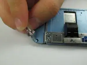
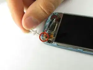
Using the pointed end of the spudger (or something sharp like a safety pin or push pin), remove the plastic screw covers along the corners of the phone.
-
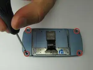
Unscrew the four 3.5 mm screws that are underneath the covers.
-
-
-
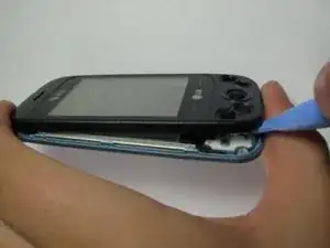
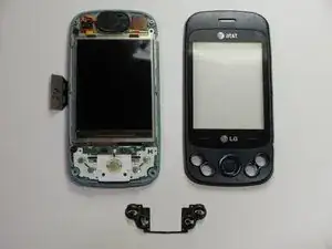
Flip the phone over. Using the plastic opening tool, remove the front casing from the phone.
-
-
-
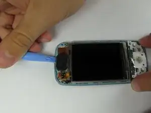
Use the plastic opening tool or the spudger to carefully remove the speaker from its casing.
-
-
-
Notice the two wires coming out of the speaker. They are soldered together onto two joints.
-
To install the new speaker, desolder these joints to remove the malfunctioning speaker using a soldering iron.
-
Solder the wires of your new speaker into the same joints.
-
To reassemble your device, follow these instructions in reverse order.
