Einleitung
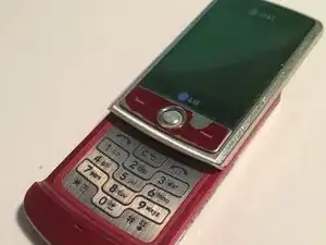
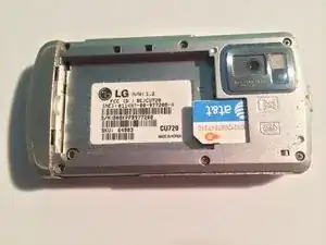
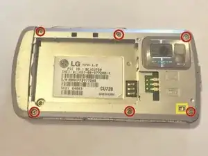
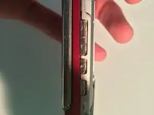
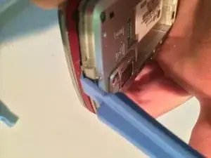
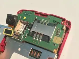
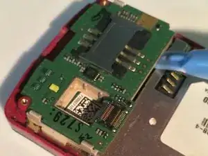
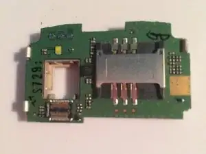
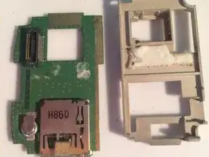
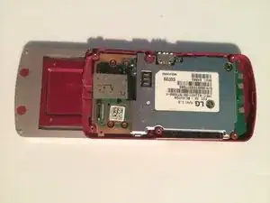
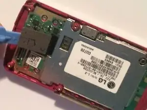
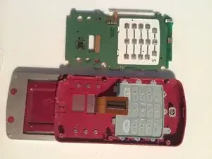
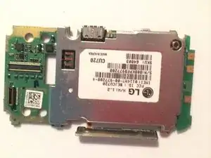
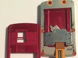
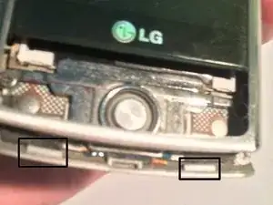
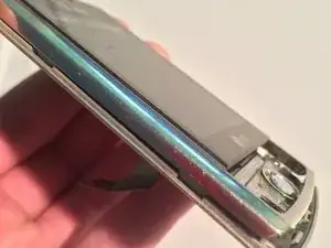
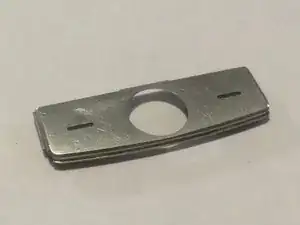
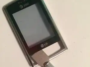
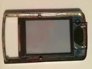
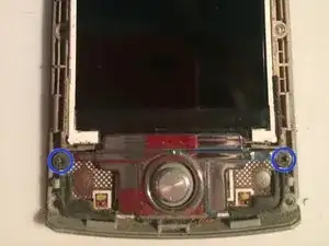
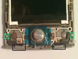
This guide will show you how to completely disassemble the LG Shine.
Werkzeuge
Ersatzteile
-
-
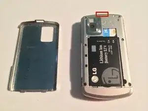
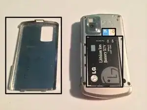
Push on the button on the top of the phone to release the battery cover.
-
Remove the battery cover, revealing the battery.
-
-
-
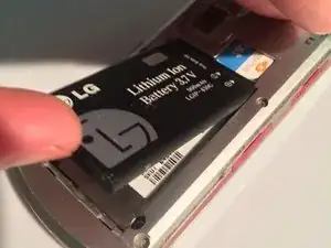
Remove the battery from the housing by prying up from the bottom.
-
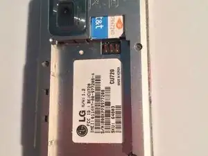
Now remove the sim card from its slot, it should pull out easily.
-
-
-
Remove the six Phillips head screws holding the back of the phone casing.
-
Be sure not to accidentally detach the grounding clip in the corner of the casing (circled in yellow) or you will have to re-adhere it for reassembly.
-
To finish removing the back casing you will need to pry 5 plastic clips loose with a plastic spudger. There is on on the top near the button, two on the bottom, and one on each side
-
-
-
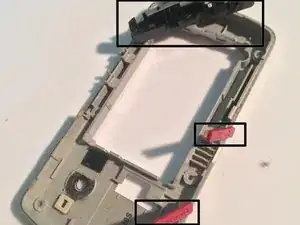
It is possible to remove and swap out these parts before reassembly: battery cover release button, grounding clip, charging and SD card slot covers, plastic/metal framework
-
-
-
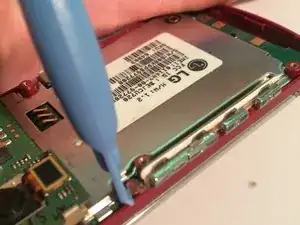
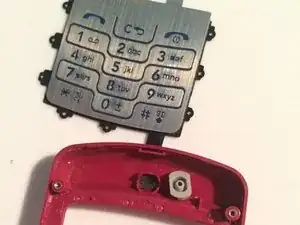
Remove the button strip by prying on the rubber pin loop on the top side of the strip.
-
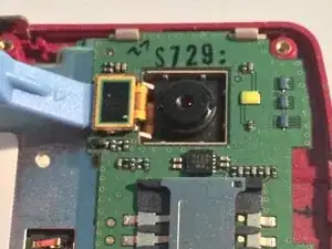
Remove the camera by releasing the ribbon cable connection with a plastic spudger, then pulling it out with tweezers.
-
-
-
Pry the ribbon cable connection up with a plastic spudger and slide the screen up.
-
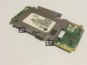
Pry each side of the phone case away from the motherboard releasing the clips to the motherboard.
-
Pull the motherboard out.
-
-
-
If needed, you can remove the metal casing around the motherboard by bending the clips and lifting up on the right side. Take note that you will have to bend back the clips for reassembly.
-
You can also remove the rubber microphone gasket if needed.
-
-
-
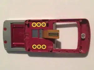
Remove the six Phillips head screws connecting the second half of the lower phone case to the sliders.
-
-
-
Remove the six Phillips head screws holding the screen casings together.
-
Remove two stickers covering two of the screws, these stickers may be reused for reassembly so don't throw them away.
-
-
-
Release all the plastic clips at the bottom under the button pad, and pry slightly with a plastic spudger, then hold constant lift pressure where the spudger is and work the rest of the clips loose.
-
-
-
Once the screen has been removed, you can replace the screen. Cleaning of the speaker dust filter is also possible.
-
-
-
Remove the two black Phillips head screws holding the joystick assembly.
-
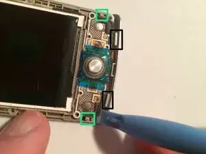
Push down on the side of the clip holding the button assembly together and pry the side of the button assembly above the clip. (repeat on each side)
-
-
-
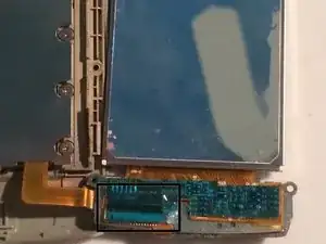
Flip over the LCD and button assembly to the right, and if covered, peel the tape on the back of the button assembly back to expose a ribbon connection.
-
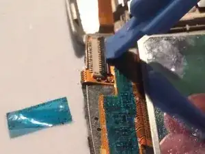
Use a plastic spudger to lift up the lock on the ribbon cable, this lets you pull the LCD out.
-
-
-
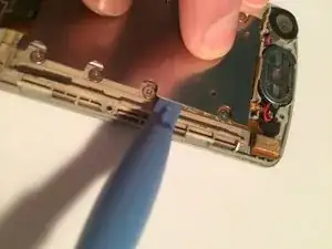
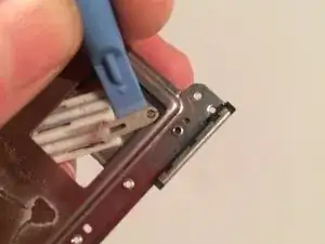
Pry out the metal backing plate where the LCD was.
-
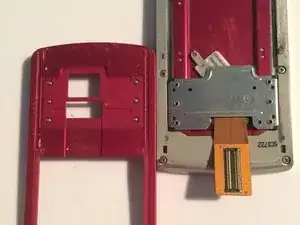
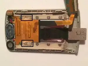
Once removed, slide the ribbon cable through the slot in the casing.
-
-
-
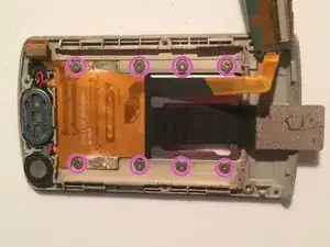
Remove the eight Phillips head screws.
-
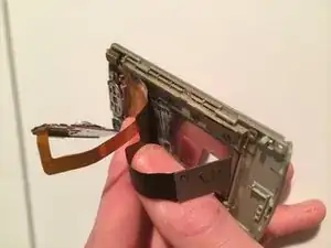
Once all these screws are removed, slowly and carefully peel the ribbon cable from the slider mechanism.
-
-
-
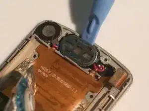
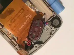
Carefully pry the speaker module out of the casing with a plastic spudger. Note that there will be adhesive holding it down.
-
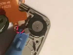
Pull the module out of the top left corner, this will also have an adhesive backing.
-
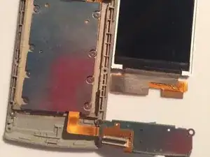
Once this is removed, the phone will be completely disassembled.
-
To reassemble your device, follow these instructions in reverse order.
