Einleitung
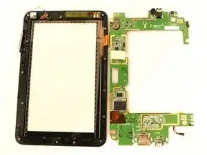
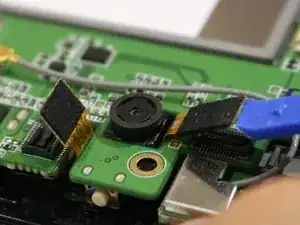
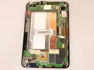
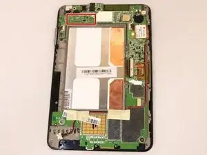
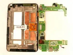
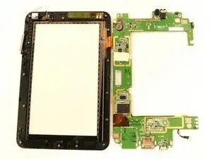
The motherboard of the Lenovo IdeaPad A1-07 may need to be replaced if the tablet has become unresponsive due to a software issue. Over time the motherboard can degrade from constant use or even crack if under a lot of pressure. This guide will walk you through how to carefully take the tablet apart to access and remove the motherboard from the device.
Werkzeuge
-
-
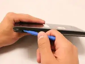
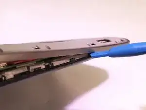
With the blue plastic opening tool, use the lock screen switch by the volume button as an access point to gently lift the back cover off.
-
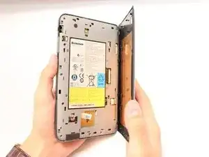
Wedge the opening tool until you start hearing the back cover popping off the body of the device.
-
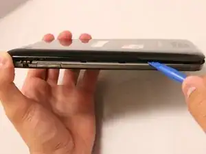
Slide the opening tool down the length of the device.
-
-
-
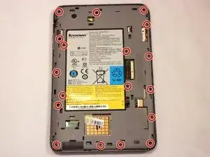
Using a Phillips #000 screwdriver, remove all 18 of the 4mm screws.
-
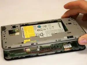
With the blue plastic opening tool, gently wedge the tool between the screen and the gray frame until you feel resistance.
-
Push in the teeth with the blue plastic opening tool, towards the center of the device, and gently pull off the frame.
-
-
-
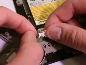
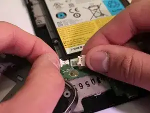
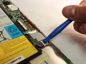
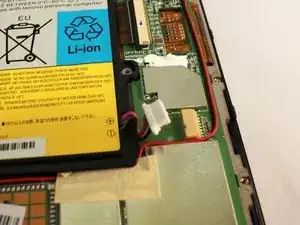
Use a plastic opening tool to push the white battery connector out of its socket on the motherboard.
-
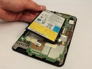
Lift the battery away from the device.
-
-
-
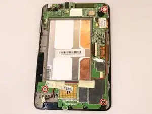
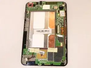
Remove the three, 3mm screws holding the motherboard to the screen using the PH #000 screwdriver.
-
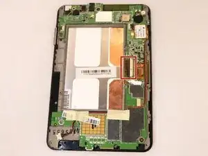
The first connector to remove is in the center of the motherboard.
-
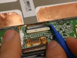
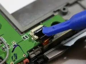
Use the blue plastic opening tool to slide the little black retainer, relieving pressure on the brown ribbon cable.
-
Use the blue opening tool to pull the brown ribbon cable out of the connector.
-
-
-
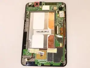
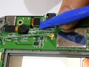
On the top left of the motherboard, to the right of the back camera is another connector.
-
To disconnect, use a blue plastic opening tool to lift and pry it up.
-
Once it snaps up out of place, it has been disconnected.
-
-
-
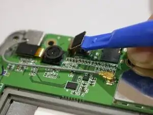
Using the same process as the previous connector, disconnect a similar connector just to the left of the back camera.
-
Once it snaps up out of place, it has been disconnected.
-
-
-
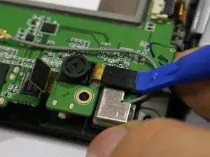
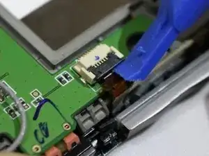
On the top left of the motherboard, just next to the volume button, is another connector.
-
Use a blue plastic opening tool to lift up on the black lever.
-
Once it is pushed up, the brown ribbon can be pulled out using the spudger.
-
-
-
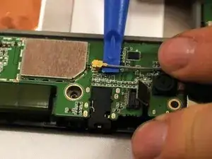
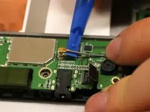
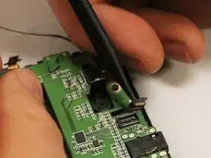
The final connector is a grey cable with a gold tip called the coaxial cable.
-
To disconnect, slide the blue plastic opening tool up to the base of the tip.
-
Twist the opening tool to gently lift up the coaxial cable.
-
-
-
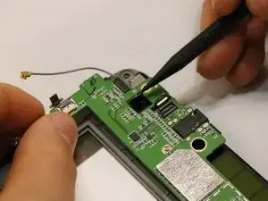
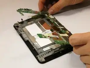
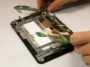
While lifting the motherboard, you need to push the connector heads down through the holes that they come through.
-
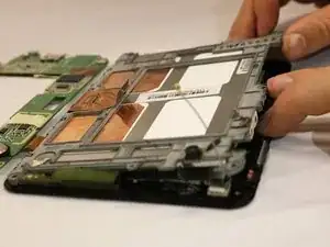
Simply lift the motherboard on the left side and flip it over to the right like turning a page.
-
-
-
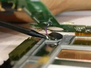
Once all the connectors are pushed through, the last thing still connecting the motherboard to the screen is the motherboard battery.
-
Using the black spudger, gently pry up the connector by pulling at the base of the battery.
-
-
-
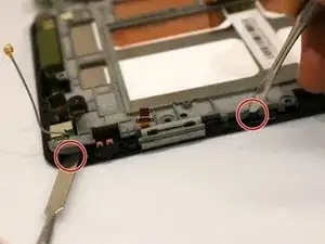
With the device face down, you can pull up on the top left side of the metal frame while pushing out a plastic tooth using two metal spudgers.
-
Gently lift until you feel the tension of the adhesive on the right side.
-
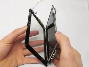
Once you feel tension, slide a metal spudger tool down the length of the right side to remove the adhesive.
-
To reassemble your device, follow these instructions in reverse order.
