Einleitung

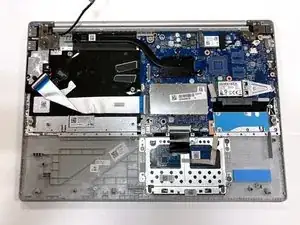
Follow this guide to replace the webcam on the Lenovo IdeaPad S340-15IWL laptop.

Issues that may indicate a faulty camera are:

  • A blank screen when using the webcam.
  • Video or images are not showing.
  • Video is blurry or out of focus.

Make sure you refer to the troubleshooting page before beginning replacement as there are many possible reasons as to why your device’s camera is not working. Many of the solutions are simple fixes and can prevent you from having to dismantle your device.

Ensure that there is no food or liquid around when you begin the repair as all of your device’s internal components will be exposed.

  1. PCo1BKIOIHWpQU5n
    PCo1BKIOIHWpQU5n
    IDrTLUE4nyumbAnG
    • Power off the laptop and place it face-down on a non-scratching surface.

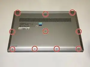
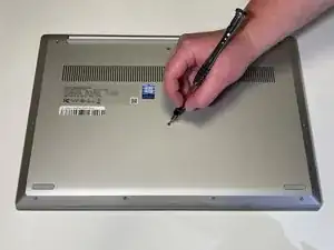
    • Using a Torx T5 screwdriver head, remove all ten 6 mm screws holding the back panel in place.

    The front center-right screw may be shorter (3.5mm) than the others (6.5mm), and may be captive in the back panel.

    Brad Bell -

  2. MixBWkKiRB1gACPo
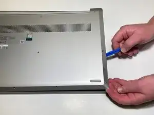
    • Slide a plastic opening tool underneath the back case near the screen hinges.

    • Gently pry up on either side of the case.

    • You may hear popping sounds as you pry up the back case. This is normal. If the case does not open, try prying at a different angle/position.

    Make sure when replacing the back cover to use the Small T5 Screw under the track pad or else the longer ones will make it so the pad wont click.

    Phillip Loftus -

  3. 1tBjmNyWYDSrawpR
    1tBjmNyWYDSrawpR
    xJELgbqKEJbyYVbM
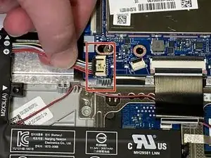
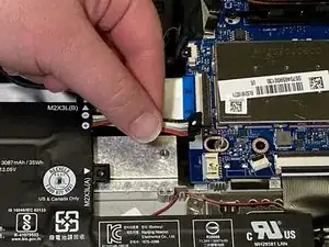
    • Disconnect the battery cable by gently pulling it straight out of the connector.

    • Be sure to pull parallel to the device to avoid bending the motherboard connector.

    • The battery connector does not lock and only requires light pressure to insert and remove.

    • Remove the battery from the laptop.

  4. xpMilYMYX15lIxON
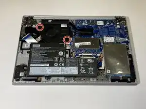
    • Remove the two 3 mm screws connecting the fan to the casing using a Phillips #0 screwdriver.

  5. SJJKxrNUvE1QiwYH
    SJJKxrNUvE1QiwYH
    wiNgSS1ETyTv4Qgs
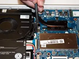
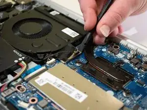
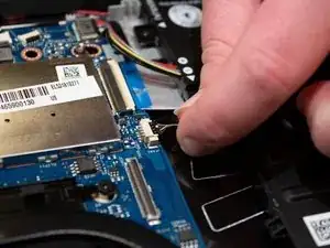
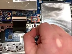
    • Using a spudger, gently disconnect the fan's cable from the motherboard.

  6. OITPgRFXVXBOYFTQ
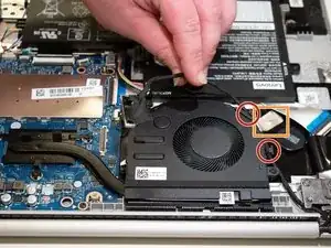
    • Carefully unwind the black cable that runs between the top of the battery and the bottom of the fan from the grooves along the side of the fan.

    • In order to do so, you will need to pull up the metallic tape that holds the cable in place using either your fingers or a plastic prying tool to lift up the edge.

    • If you attempt to remove the device’s fan without removing the battery, the black cable may be wedged underneath the top of the battery. In this scenario, it is recommended that you at least loosen the screws holding the battery in place to allow for the cable to be removed with less resistance.

  7. PjcRV4t5D45EEXcS
    PjcRV4t5D45EEXcS
    sm1uCsVUA14U6FHE
    K1rqZF6sBGF1cgVg
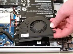
    • Carefully pick up the fan by the corners and detach the small connector wire by pulling parallel to the device.

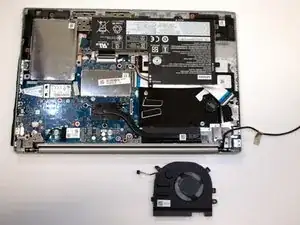
    • Remove the fan from the laptop.

  8. aJl6cQbP3sNBsWUo
    aJl6cQbP3sNBsWUo
    QGulAvXa5E11ipUk
    YVDtiehwEbctWKOJ
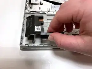
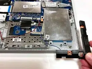
    • Unplug the wire connecting the speakers to the motherboard.

    • Remove the speakers from each side of the laptop.

  9. 4tN5a4twJSZZyOSj
    4tN5a4twJSZZyOSj
    TNLkYG65KBsHPj1s
    6H3mS3bxTTwlCwea
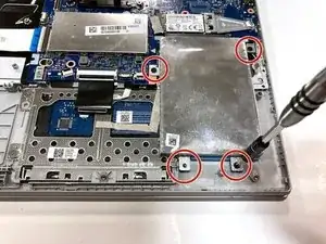
    • Remove the four 3 mm screws holding the hard drive expansion slot in place using a Phillips #0 screwdriver.

  10. LxCKCZMdjhcqcHI4
    LxCKCZMdjhcqcHI4
    EeLsbQUWxFQmCRQw
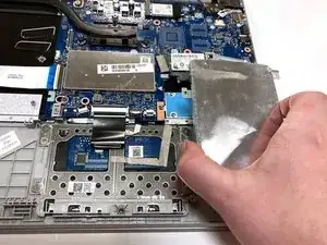
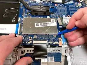
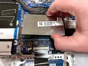
    • Using the opening tool, gently pop off the metal cover for the RAM stick.

  11. YwavJNOhiuMVYJGM
    YwavJNOhiuMVYJGM
    KpMXLPtGxCEJAHQr
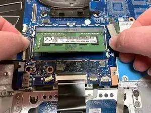
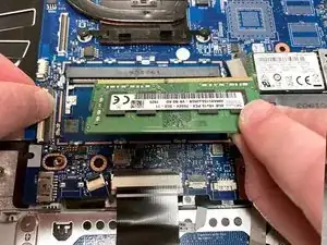
    • Using your thumbs, gently pull the two metal prongs that secure the RAM outwards.

    • The RAM will pop up at an angle.

    • Remove the RAM from the laptop.

  12. CGLQpRYjW66iLFiD
    CGLQpRYjW66iLFiD
    Qrvk4ZAyr6JgHQLa
    hElkmtRUHNrHMPBZ
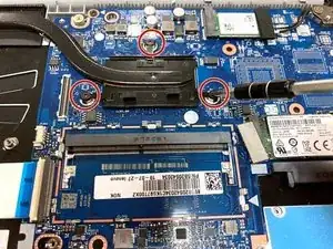
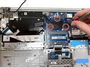
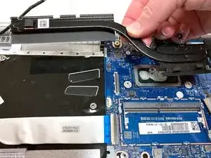
    • Remove the three 3 mm screws that secure the black heat sink near the top of the computer using a Phillips #0 screwdriver.

    • Lift the heat sink vertically to remove it from the laptop.

  13. OlAAA4Ud6McfbOc3
    OlAAA4Ud6McfbOc3
    JI1o2XKsdV1SkSPw
    wZRpe5fQyERM4ZXY
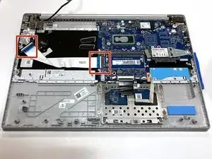
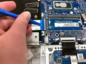
    • Using an opening tool, carefully flip up the retaining flaps holding the silver video cable in place.

    • Slide the ribbon cable out of each connector.

  14. VqEG1je5yIhLbMrD
    VqEG1je5yIhLbMrD
    pGIpFeaQi36pNV4p
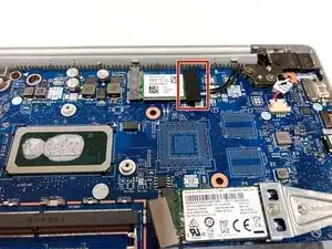
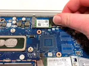
    • Pull up the black foam adhesive that covers the screw and connectors holding the Wi-Fi card in place.

  15. QIJjw4ugQGXPpwlv
    QIJjw4ugQGXPpwlv
    nAAMINCkWoEYwm3V
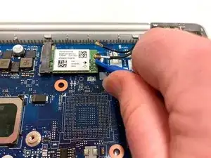
    • Using an opening tool, lift up on the black and white coaxial cables on the Wi-Fi card and gently pull upward to unplug them.

    • When reconnecting the cables, be sure to match the colors to the arrows on the Wi-Fi card.

  16. DjQKDCwn4NRqMXYP
    DjQKDCwn4NRqMXYP
    anHkgPrE1ZKqBKPl
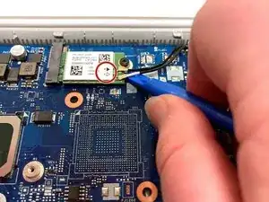
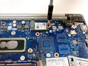
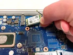
    • Remove the single 3 mm screw holding the Wi-Fi card in place using a Phillips #0 screwdriver.

    • Gently lift the Wi-Fi card out of the computer.

  17. P3tDS1hXIs4tY1TM
    P3tDS1hXIs4tY1TM
    wo55qaUtTtvnMr4o
    XJ5nREl3GkOu5Gdf
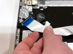
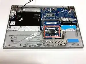
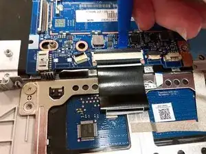
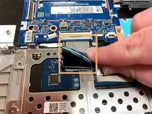
    • Using an opening tool, flip up the retaining flap that holds the connector to the thin black ribbon cable at the bottom of the motherboard.

    • Gently remove the ribbon cable from its connector.

    • The cable is folded over and connected to itself with an adhesive. Be careful to only pull at the top fold of the cable.

  18. o6xTeoXlieVZ2nDR
    o6xTeoXlieVZ2nDR
    XmakyChHrXVHCaLP
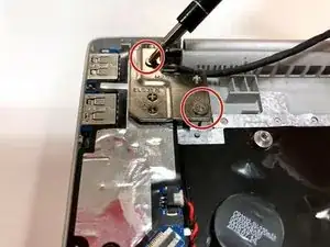
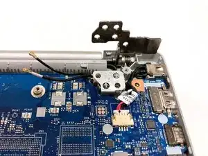
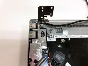
    • Remove the three total silver 6 mm screws from the hinges of the screen in the top corners of the device using a Phillips #0 screwdriver.

  19. wukvDSv5BFapYpVS
    wukvDSv5BFapYpVS
    JWFQDN63sAEP26KK
    HjywQnhNWqxBoGEf
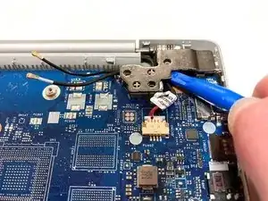
    • Use an opening tool to flip up the hinges.

    • You may have to apply some force.

  20. NyOQooPOcrXg5CUJ
    NyOQooPOcrXg5CUJ
    iXQ5Ux3XSgd4vRE6
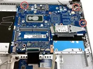
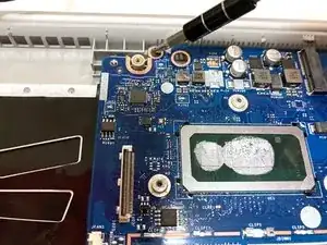
    • Remove the three 3 mm screws holding the motherboard in place using a Phillips #0 screwdriver.

  21. oCWql6Nd5AyT51Bo
    oCWql6Nd5AyT51Bo
    UhrgbY5HUSyxHIPf
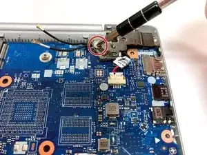
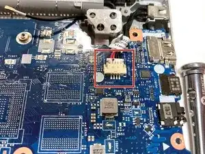
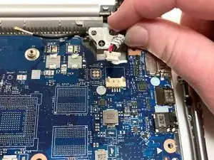
    • Carefully unplug the black and red wires connected to the upper right corner of the motherboard.

    • These wires connect to the device’s charging port.

  22. AXSTCflr3qECdtbf
    AXSTCflr3qECdtbf
    S2MxlATVT5FwhoCD
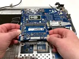
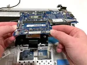
    • Carefully lift the motherboard from the base of the computer and remove it from the laptop.

  23. ok1CORAT2J3iRhOR
    ok1CORAT2J3iRhOR
    livn1gSGJrLTfnuL
    BhFuPnYEUHFHlZXD
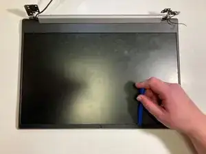
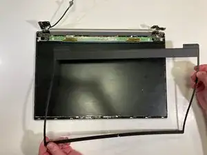
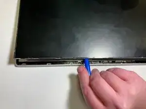
    • Using an opening tool, carefully pry up and remove the plastic bezel casing surrounding the screen.

  24. 6icwK4KDdqnkNWBs
    6icwK4KDdqnkNWBs
    Vc5T2QSBxsJxeuMK
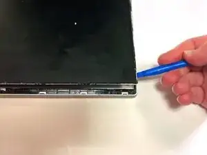
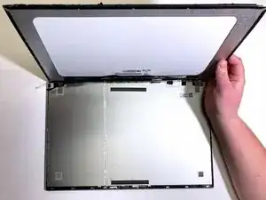
    • Using a plastic opening tool, very carefully begin to remove its casing.

    • Be EXTREMELY careful when removing your screen. Make sure that your prying tool is wedged completely under the screen and the foundation holding it in place; it’s easy to accidentally insert the tool into the LCD itself and crack the screen.

    • The screen is held to the casing with a few strips of extremely strong foam adhesive. If possible, it is best to use the prying tool to separate the adhesive from the screen before attempting to remove it.

  25. Zmv2fxhbIwNHXnnx
    Zmv2fxhbIwNHXnnx
    PCIJivjeddHMoIr5
    wGGIQIJKq25xjISX
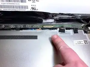
    • Lift the display up very carefully.

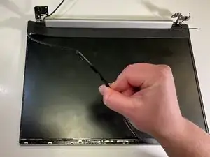
    • Beneath the electrical tape protecting the circuit board is a small black and gold cable.

    • Gently unplug this cable, and then remove the screen from the casing.

  26. tww4CedMAWQZn2uf
    tww4CedMAWQZn2uf
    gmumTf6ovjtLdpqg
    VYZxQN1PtBjNp2It
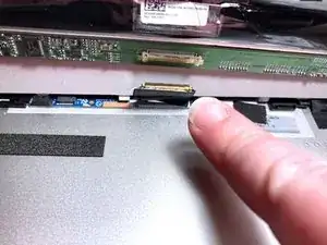
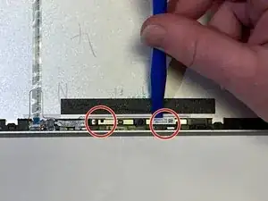
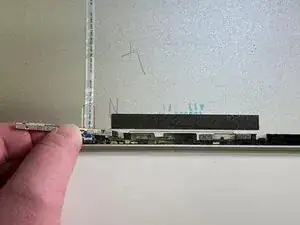
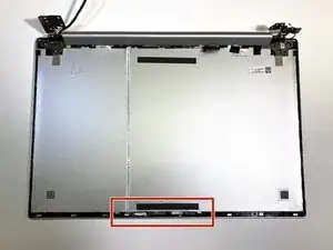
    • Under the device’s screen, there is a small cable running up the middle of the device which is connected to the device’s camera.

    • Using an opening tool, gently pop the camera off of the two plastic connection points holding it in place.

    • The camera itself is quite small and somewhat difficult to see.

    • In addition to the plastic connection points, the camera is also connected to the casing with a foam adhesive. You may have to pull this adhesive strip off instead of prying it out of place.

  27. nFfNZ3WWQAGUPcMc
    nFfNZ3WWQAGUPcMc
    dBDAHWLO4q3h3HgE
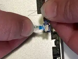
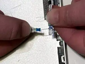
    • After loosening the connection cable from the casing, gently pull out the blue chip connecting the cable to the camera.

    • The blue chip is extremely small and bends easily. Apply as little force as possible while both removing and reinserting it.

Abschluss

To reassemble your device, follow these instructions in reverse order.
Christine Robbins

Mitglied seit: 17/09/21

467 Reputation

0 Kommentare