Einleitung

This guide will demonstrate the process of replacing the motherboard in the Lenovo Yoga 900-13ISK. The motherboard handles computations for the laptop, and manages the inputs and outputs of all the other components. The motherboard is also home to the CPU and RAM, so any issues commonly associated to a failure with one of these components can be solved with a motherboard replacement. Common symptoms of a faulty motherboard in the Lenovo Yoga 900 are glitchy graphics, frequent crashes or freezes, the computer not turning on, and booting to an error screen. If you are experiencing any of these issues, and have ruled out a lesser component as the culprit, a motherboard replacement should help solve the problem.

The motherboard in the Lenovo Yoga 900 is connected to the heatsink and fan assembly, and these components will be removed from the computer as a single unit. If your replacement motherboard does not include the heatsink and fan assembly, you can transfer over your old cooling system using this heatsink guide.

Be sure to unplug and completely turn off your device before you start working.

  1. iPv1VlyTxQxoxqa5
    iPv1VlyTxQxoxqa5
    YlbrhAqDnTIYRgTM
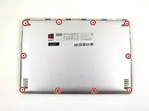
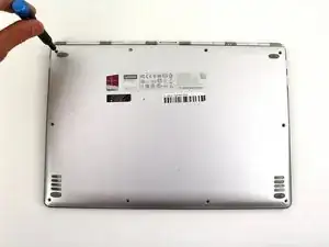
    • Using a T5 Torx screwdriver, remove the ten 5.5 mm screws from the back case of the laptop.

  2. WrCrfbcYMa2QYBT2
    WrCrfbcYMa2QYBT2
    1hYBLMYwmAkKeVdk
    WDk2DgNOfV1YrZSE
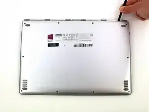
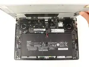
    • Use a spudger to pry open the back case at the hinges of the laptop.

    • There are plastic clips around the perimeter of the case holding down the back cover. These will need to be popped off as the cover is removed.

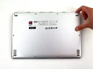
    • Use your fingers to completely pop off the back cover.

  3. QkgyYHZ1WljCk3P3
    QkgyYHZ1WljCk3P3
    Dbetc2r2Cr25kmeS
    OA1xH5HoUihZRLPW
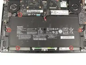
    • Remove the five 3.6 mm screws from the battery with a Phillips #00 screwdriver.

  4. k3RABbhhBKAQO1s3
    k3RABbhhBKAQO1s3
    6MfLagnBnV4YTOso
    nftRq1KFHOCYplHV
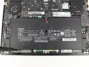
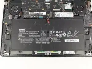
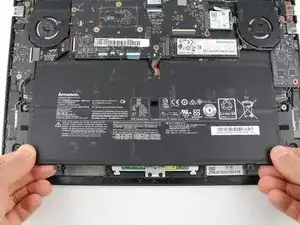
    • Grab the bottom corners of the battery and gently pull the battery until the cable disconnects from the connector on the motherboard.

    • While reassembling, use a plastic spudger to push the battery cable into the connector on the underside of the motherboard. This will be easier to do before the screws are replaced.

  5. RvfoDVyFqQPx2xTe
    RvfoDVyFqQPx2xTe
    OHDDUBMShPlS6LbN
    BxjQCW1iHD2bst6s
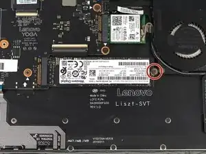
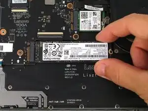
    • Use a Phillips #00 screwdriver to remove the 2.7 mm screw that is holding down the SSD card.

    Stop! Before you remove anything else, you can just un-secure the fan assm and lift it up to get the power connector cable out. This only requires removing the NGFF wifi card. You DON'T need to remove the motherboard like this guide recommends, just take care to not bend the heat pipe up too high as you lift the fan assembly, as it is quite fragile.

    Avery Freeman -

  6. Vltut52aUdGVNYRS
    Vltut52aUdGVNYRS
    2yNHZXMeVyle5bk2
    oKAyaMRIkQEa6Ukl
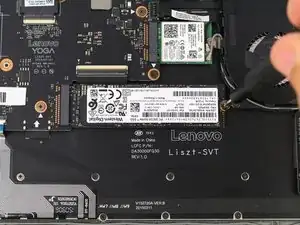
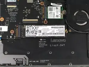
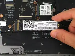
    • Pull the SSD card out of the port to the right.

  7. XRIgqtv2noDGTMCL
    XRIgqtv2noDGTMCL
    lfmTP6IOYilUQBTX
    pInKbZfVdAqUfo5K
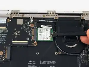
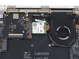
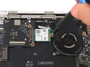
    • Pry up the gray and black coaxial cables from the Wi-Fi card using a spudger.

    • Move the cables to the side.

  8. FXe2vn2F6x5KvrTj
    FXe2vn2F6x5KvrTj
    vL22JsqQtabGogrq
    BYoKUuO6Wb1OMvAA
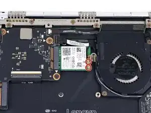
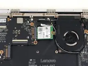
    • Using a Phillips #00 screwdriver, remove the 2.2 mm screw holding down the Wi-Fi card.

    • The Wi-Fi card may pop up to rest at an angle to the motherboard after the screw is removed.

  9. 6oeG3GaPL3Re3Cu5
    6oeG3GaPL3Re3Cu5
    ZcbVeKKkwIXQYHfq
    hJvx2FNyWu4lRu1Y
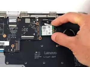
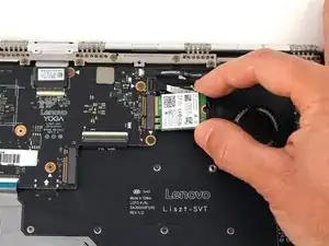
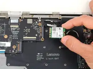
    • Pull the WiFi card out from the connector on the motherboard.

  10. 2iPXHr2mKTxOLDMU
    2iPXHr2mKTxOLDMU
    WBVXYlpcgW2xsvBX
    kAs31xGjYJTiIEqK
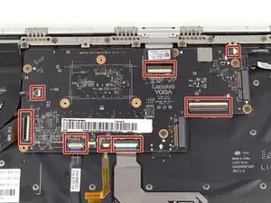
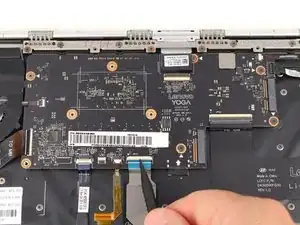
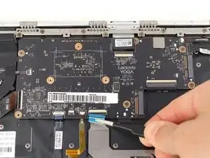
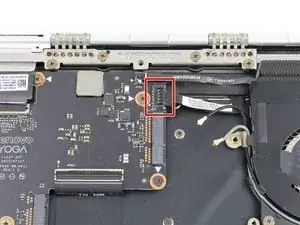
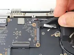
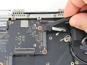
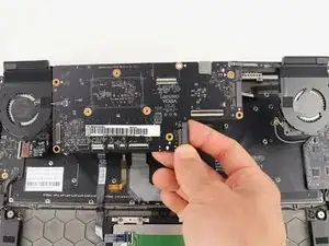
    • Using the pointed end of a spudger, flip up the hinged locking tabs of the eight ZIF connectors on the motherboard.

    • Pull the eight cables out from their connectors using a pair of blunt nose tweezers.

    It is not necessary to open the 2 small connectors for the fans

    Torsten Sadowski -

  11. RDXDAFFswqiWbfqL
    RDXDAFFswqiWbfqL
    yFZWjMRRNKnIehsw
    6LUOWnmZHDCNa5dL
  12. ZasHp1ZdfanEYIwD
    ZasHp1ZdfanEYIwD
    vxmG5GAiaQuC2ymG
    YXnEvPZkqqvCjAxe
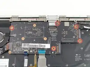
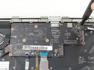
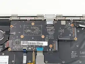
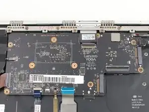
    • Remove the five 3.6 mm screws from the motherboard using a Phillips #00 screwdriver.

  13. 6bpntfEhDkXkTPmX
    6bpntfEhDkXkTPmX
    Yu1wsmUJMuqcnrVS
    FnYECEJOmjhTDMEC
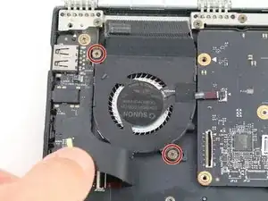
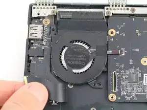
    • Pull back the interconnect cable on the left side of the motherboard to reveal one of the fan screws for the left fan.

    • Remove the two 3.6 mm screws from the left fan with a Phillips #00 screwdriver.

  14. Ls31jPxxmxIsV42s
    Ls31jPxxmxIsV42s
    IBehbPinVoSEUuAl
    N51FEHUXIcrF1vJw
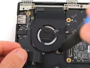
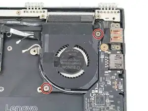
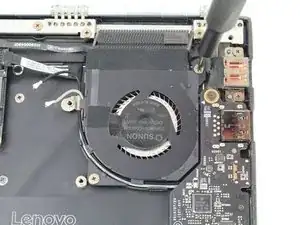
    • Remove the two 3.6 mm screws from the right fan using a Phillips #00 screwdriver.

  15. tfJjpiwrqohL1MuL
    tfJjpiwrqohL1MuL
    SYoBpglDmKZlh3fV
    wXUVJUkwnMSC3K4D
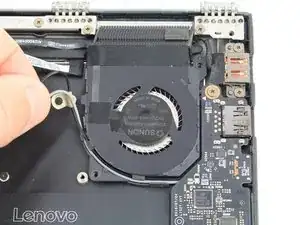
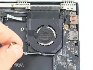
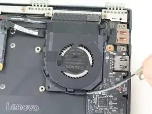
    • Unwind the black and white coaxial cables from the hooks on the right fan casing.

  16. XCtmXrLyAvX5KhVU
    XCtmXrLyAvX5KhVU
    F11hPEuuVrvX4UDr
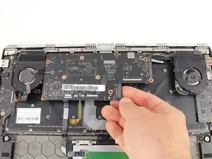
    • Lift the motherboard from the bottom edge and pull it up and out of the case.

    • If you need to remove the fan assembly to swap it over to your new motherboard, continue to follow along with the heatsink guide.

Abschluss

To reassemble your device, follow these instructions in reverse order.
Austin Blakely

Mitglied seit: 11/03/19

17060 Reputation

0 Kommentare