Einleitung

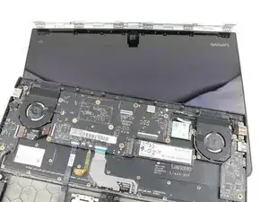
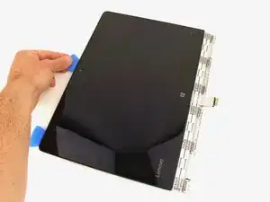
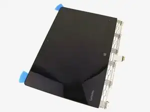
This guide will show you how to replace the webcam in your Lenovo Yoga 900-13ISK. The webcam allows the user to engage in video calls, so it’s especially essential in this day and age. The webcam will typically fail completely, throwing up an error when the computer tries to use it or displaying a black screen where webcam video feed should be displayed. However, it’s also possible for the webcam to display glitchy or blurry video, in which case a webcam replacement will also need to be performed.

Be sure to restart the computer and try any known software fixes to try to get your webcam working again before diving in for a replacement.

You also may want to purchase replacement adhesive for the display assembly, as your display may not stick together perfectly once the old adhesive has been cut away. Be sure to remove and clean any old adhesive before applying the fresh adhesive.

Be sure to unplug and completely turn off your device before you start working.

  1. iPv1VlyTxQxoxqa5
    iPv1VlyTxQxoxqa5
    YlbrhAqDnTIYRgTM
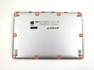
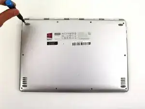
    • Using a T5 Torx screwdriver, remove the ten 5.5 mm screws from the back case of the laptop.

  2. WrCrfbcYMa2QYBT2
    WrCrfbcYMa2QYBT2
    1hYBLMYwmAkKeVdk
    WDk2DgNOfV1YrZSE
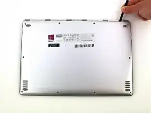
    • Use a spudger to pry open the back case at the hinges of the laptop.

    • There are plastic clips around the perimeter of the case holding down the back cover. These will need to be popped off as the cover is removed.

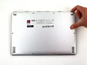
    • Use your fingers to completely pop off the back cover.

  3. QkgyYHZ1WljCk3P3
    QkgyYHZ1WljCk3P3
    Dbetc2r2Cr25kmeS
    OA1xH5HoUihZRLPW
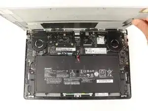
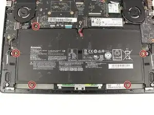
    • Remove the five 3.6 mm screws from the battery with a Phillips #00 screwdriver.

  4. k3RABbhhBKAQO1s3
    k3RABbhhBKAQO1s3
    6MfLagnBnV4YTOso
    nftRq1KFHOCYplHV
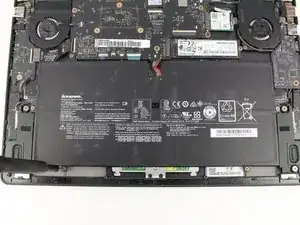
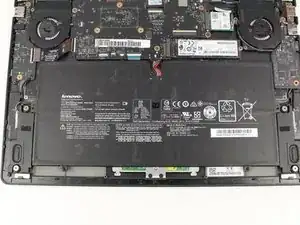
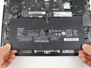
    • Grab the bottom corners of the battery and gently pull the battery until the cable disconnects from the connector on the motherboard.

    • While reassembling, use a plastic spudger to push the battery cable into the connector on the underside of the motherboard. This will be easier to do before the screws are replaced.

  5. gmKKJjXftoRvBsgL
    gmKKJjXftoRvBsgL
    OLjETtD6ln2iMrbN
    RgyLvePQsoBOOJKD
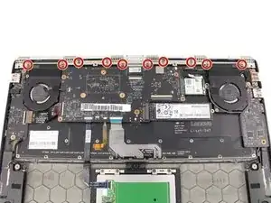
    • Remove the ten 3.6 mm screws from the hinge bracket with a Phillips #00 screwdriver.

  6. 6qNPfuLRpkwNS56U
    6qNPfuLRpkwNS56U
    nQqDWop3NfoS6Xym
    FU6VHwaCmfOwEcQx
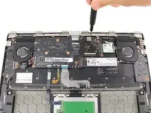
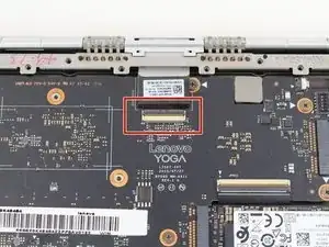
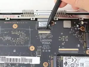
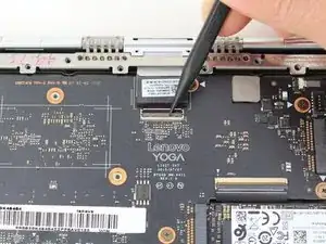
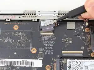
    • Use the pointed end of a spudger to lift the hinged locking flap of the display ZIF connector.

  7. gdMehidtVAUmKlvT
    gdMehidtVAUmKlvT
    SyxoUiWeyirdNVWA
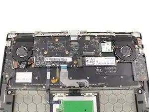
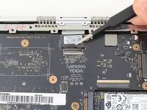
    • Pull out the display cable with a pair of blunt nose tweezers.

  8. To11u44fJTXcIO4I
    To11u44fJTXcIO4I
    y3TkGGjm21KVTknd
    OvIbYNI1whZDxOff
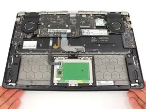
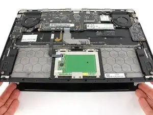
    • Open the laptop to a 45° angle, then close the laptop.

    • This raises the hinge, which will stay open as the bottom case is lowered.

  9. CfCCR5f2bASYi1UZ
    CfCCR5f2bASYi1UZ
    vJkYXiVlGFgGgLqA
    4pMIG35vyQFEq5Rs
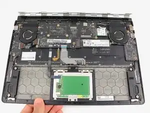
    • Slide the bottom case away from the hinge.

    • If the hinge is catching on the case, either go back to the previous step and open the case a bit more, or manually open the hinge with your fingers.

  10. SauIWYOEkmZZSaEG
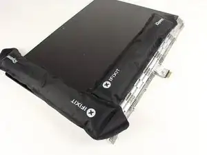
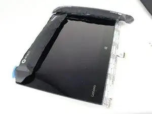
    • Apply heat along the bottom and left edges of the screen, either with a heat gun or iOpener.

    • Check out our iOpener Instructions if you need help!

  11. nlsREYQ1OdEaQ6fb
    nlsREYQ1OdEaQ6fb
    pQNkSJDLSrnS1dtL
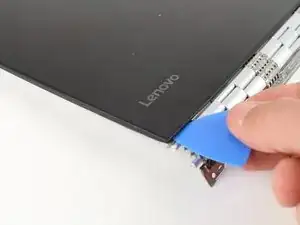
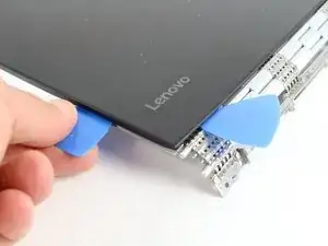
    • Insert an opening pick into the corner of the screen and slide it around slightly to create an opening.

  12. aLai4MhWAKWnJcNy
    aLai4MhWAKWnJcNy
    1y1bG5LIIYDgQnU4
    c2h3jiW2IkStAUCl
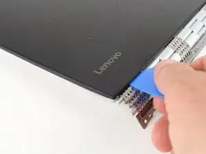
    • Insert a second opening pick and slide it along the side of the display, cutting away the adhesive.

  13. WCAFALE41HwuyXNE
    • Use a heat gun or iOpener to apply heat to the top and side edge that have not yet been opened.

  14. o1MDvo52XRssRCL2
    o1MDvo52XRssRCL2
    etImlVpjmKKoIp6A
    4XxhPK24qL2CAwCo
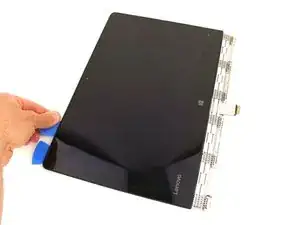
    • Continue cutting away the adhesive on the top and side edges of the display.

  15. 5gMHBQFYdlG41sgd
    5gMHBQFYdlG41sgd
    1Gl3iGBFvTF21qb1
    JCvuPGWj5XQHEGeA
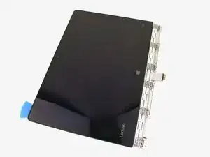
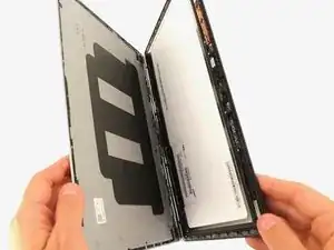
    • Open the display casing along the top edge.

  16. YTqUgpBX4gPZTiyp
    YTqUgpBX4gPZTiyp
    hpZZlKkvXovnDHug
    Zfkdpofr4SAEEjTd
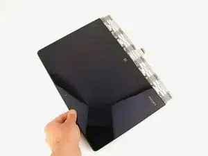
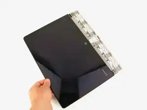
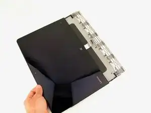
    • Pull the display cable out from the hinge mechanism.

  17. YJEJNyMfsywccJHH
    YJEJNyMfsywccJHH
    E2TeiaHic5KpiKVp
    Od6d41PEcLAPrmhf
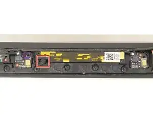
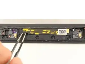
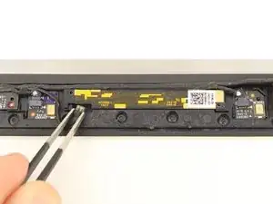
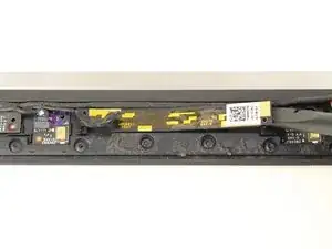
    • Gently remove the cable from the yellow-accented webcam board on the top of the display panel with a pair of blunt nose tweezers.

  18. pbyMeOseAJFkvEED
    pbyMeOseAJFkvEED
    HcF33EOgFflq2Ms6
    5Jg3G1SMdMI2Y3Bi
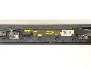
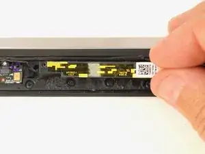
    • Gently lift up the webcam board with a spudger.

    • There will be strong adhesive holding the board in place, so be careful not to bend or break the delicate board.

Abschluss

To reassemble your device, follow these instructions in reverse order.
Austin Blakely

Mitglied seit: 11/03/19

17060 Reputation

0 Kommentare