Einleitung
Werkzeuge
-
-
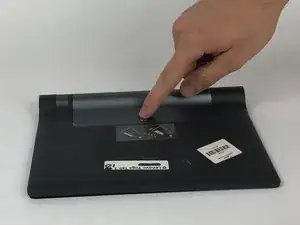
Open the kickstand by pressing the release button in the center.
-
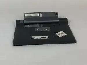
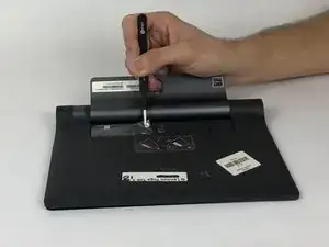
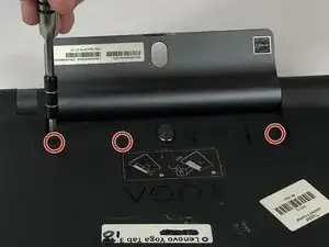
Remove the identification sticker with a pair of tweezers to allow access to the two 2mm screws underneath.
-
-
-
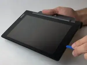
Starting along the edge opposite of the hinge, insert a plastic opening tool between the screen and the backing to begin separating the small clips holding the backing on.
-
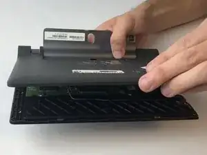
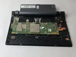
Work along the edge and then up the sides, separating the clips with the plastic opening tool.
-
-
-
With the tablet oriented screen side down and hinge opposite of you, locate the black plastic piece on the top right.
-
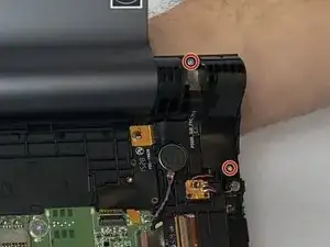
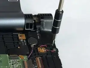
Remove the upper 4mm and lower 3mm screws with a PH00 screwdriver.
-
-
-
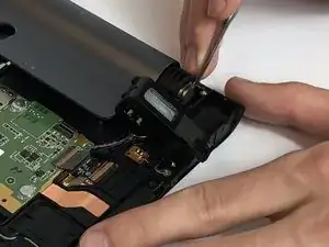
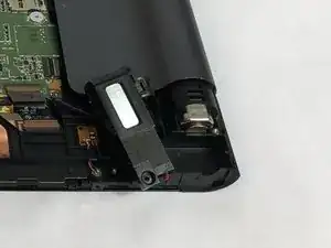
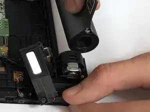
Position the kickstand to an almost closed position. Carefully move the plastic block aside and pry the metal lock out with a metal spudger.
-
-
-
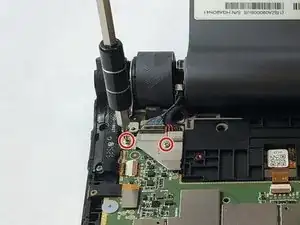
At the opposite end of the hinge, locate the silver metal bracket over the wires coming from the end of the hinge. Remove the two 3mm screws with a PH00 screwdriver. Lift the bracket off with your fingers.
-
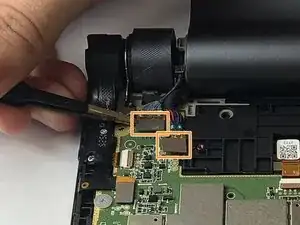
Removing the bracket will expose two silver connectors at the ends of the wires coming from the end of the hinge. Use tweezers to carefully lift off the two silver connectors.
-
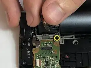
Locate the smaller metal wire bracket guiding the wires coming from the end of the hinge. Remove the single black 2mm screw with a PH00 screwdriver. Lift the bracket off with your fingers.
-
-
-
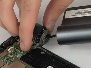
Begin removing the entire hinge assembly by lifting it out, starting at the end where the lock is located. Carefully feed the wires through the hinge mount with your fingers as you pull the hinge assembly free.
-
To reassemble your device, follow these instructions in reverse order.
