Einleitung

Wenn dein Logitech G27 nach der Kalibrierung nicht mehr reagiert, musst du möglicherweise den optischen Encoder tauschen. Der optische Encoder ist ein kleines Bauteil, das die Raddrehungen in elektrische Signale für den Computer umwandelt. Das zu ersetzten ist nicht schwer, braucht aber viel Geduld, weil du sehr viele Schrauben lösen musst. Stelle sicher, dass das Lenkrad nicht angeschlossen ist, bevor du beginnst.

  1. JFe3hZpcNcMwfMMY
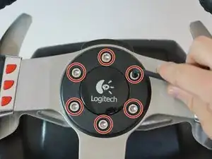
    • Entferne die sechs grauen 25mm Sechskantschrauben mit einem 4mm Inbusschlüssel.

    • Sei vorsichtig, wenn du das Rad hochhebst, da an der Unterseite zerbrechliche Drähte hängen.

    • Hebe das Rad vorsichtig an, trenne es jedoch nicht vom Rest des Geräts.

  2. wnfiUv2VBuSB31AK
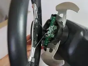
    • Hebe vorsichtig das Rad von der Nabe ab und lege die 2 Schaltpaddeldrähte und die Platine frei.

  3. NZhmVBB6Bqh3Wu2P
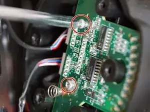
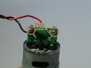
    • Entferne die beiden 7,5 mm silbernen Schrauben, die die grüne Platine im Rad befestigen, mit einem Kreuzschlitzschraubendreher # 1.

  4. foUkt5y4AwJkc2ET
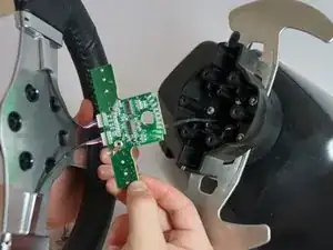
    • Entferne vorsichtig die Platine von der Radnabe.

  5. Qtmlc6TkePtrVyam
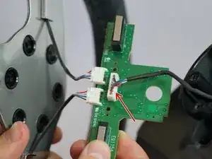
    • Fasse vorsichtig den großen 7-poligen Stecker unter der Platine und ziehe ihn ab.

    • Sei vorsichtig, wenn du diesen Adapter abziehst, versuche, nicht an den Kabeln zu ziehen, um sie nicht zu beschädigen. Wackle stattdessen um den Kunststoffverbinder herum, während du daran ziehst, um ihn zu lösen.

    These screws refused to go all the way back in for me, and one of them stripped completely. If this happens to you, you can get replacement screws that are shorter here - https://www.amazon.com/gp/product/B01MFA...

    This works for the G27, not sure about the G25 or any other wheels.

    Obviously the screws being shorter means the wheel isn't as strongly attached to the base in this direction, so if you have to do this remember not to put unnecessary stress on these screws by pulling the wheel straight off the base.

    SouthernPotato -

    bro i need new long cable i think and that connector or just replace the whole thing .. i put new grease, screw it more tight by the encoder so it woulnt go to the left .. wheel works verry nice tho all my buttons and shifter pedals wont work now tho the lights works dont know what to do now.. and now i kinda regreat opening it.. my wheel run so good now just these buttons are off not working at all and it kinda screws up midle of the game..

    Alexander -

    @alexdinpoik I’ve had the same problem when the 7 pin connectors blue and green cables broke off. First, only the blue one was broken which only took the led indicators gradual increase but all buttons were working then when i tried to plug in back, the green one broke off leading to none of the buttons working but the led indicators just working. Now i’ll try to fix it with iron soldering.

    Okan Akgül -

    okan can u pls share a video of you doing it? so i can do the “copy paste” hahah where can i buy cables and stuff i need for that? whats the name of these white connectors ? im new to this but share me a link to buy. i rather just try to fix it then buy a new wheel since its a great wheel compare to g29 that has bad software and the other wheels are to expensive. g27 cant be found in stores anymore neither and if im gonna buy one it has to be new haha hopefully u can share some knowlage thanks!

    Alexander -

    Where i can Buy the 7 pin cable for Main board please

    Ojilve jose -

    Hey guys!

    i broke the 7 pin cable anyone know where can is buy it? Thanks

    Richard Hajdu -

  6. FiRu5bFZLB5YBEuV
    • Du kannst das Rad jetzt vollständig von der Nabe entfernen. Lege es beiseite, bis du das Rad wieder zusammensetzt.

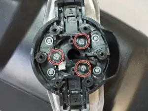
    • Entferne die innersten drei 37,5 mm silbernen Schrauben mit einem Kreuzschlitzschraubendreher # 1.

    • Entferne die Radnabe und schiebe den Stecker durch die Mitte der Nabe.

  7. hRAYY1mMrAVKZJFD
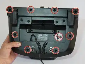
    • Lege die Radnabe zur Seite und drehe das Lenkrad Gehäuse herum, um an die Unterseite heranzukommen.

    • Entferne die acht silberfarbenen 15,9 mm Kreuzschlitzschrauben #1 am Rand der Unterseite des Lenkradgehäuses.

  8. UidVkwPtGC2eJLMK
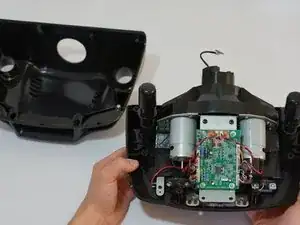
    • Drehe das Gehäuse wieder um und entferne die obere Gehäusehälfte, so dass die meisten Bauteile des Lenkrads sichtbar werden.

    • Lege die obere Gehäusehälfte zur Seite, du brauchst sie erst beim Zusammenbau.

    need two new black screes abouve the pcb board.. lost them need to know the size since the screws i replace it with was not exact..

    Alexander -

    Loosen the desk clamps before removing the housing, otherwise you risk breaking something. The housing should come off without having to use any force whatsoever.

    Oula Kuuva -

  9. AmPXsBqhnwifCPIb
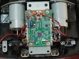
    • Entferne die vier silberfarbenen 7,3 mm Kreuzschlitzschrauben#1, mit denen die grüne Leiterplatte am Motorgehäuse befestigt ist.

    I’d do steps 9 and 10 in reverse order, the connectors are much easier to unplug while the board is secured in place.

    Oula Kuuva -

  10. CyrTKTeAZ5fqJSPi
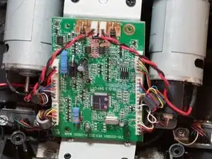
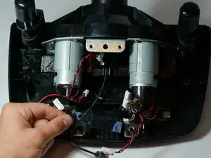
    • Löse die drei Plastikstecker an der linken Seite der Leiterplatte.

    • Löse die beiden Plastikstecker oben an der Leiterplatte.

    • Löse die drei Plastikstecker rechts an der Leiterplatte.

    • Zum Abziehen der Stecker brauchst du ziemlich viel Kraft. Sei aber vorsichtig und ziehe nicht direkt an den Kabeln. Versuche die Steckerseite der Verbinder herauszuhebeln.

    • Beim Heraushebeln der Stecker kann eventuell ein Öffnungswerkzeug aus Kunststoff helfen.

    • Durch den Ausbau dieser Stecker erhältst du leichteren Zugang zu den vier Schrauben der Leiterplattenbefestigung am Motorgehäuse.

    Some of the connectors have locks on them, I would recommend this as a two person job.

    Reuben Andrews -

    I didn't take them off :)

    Evaristo Rivieccio Vega -

    I messed up and broke the cables of the 5 Pin Connector on the right. Can anyone tell me what it’s called so I can buy replacement? The Rest of the cable is stuck in there so I can’t re-use it sadly.

    Felix Weschke -

  11. a4odqtXHQyqDcUbg
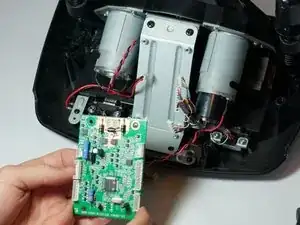
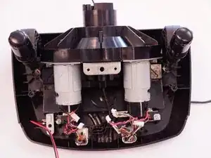
    • Wenn alle Stecker gelöst sind, kannst du die Leiterplatte entfernen.

    • Lege sie zur Seite.

  12. Hvf5BHMD5r3wZDec
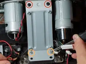
    • Entferne die oberen zwei schwarzen 12,3 mm Kreuzschlitzschrauben #2.

    • Entferne die unteren zwei silberfarbenen 15,5 mm Kreuzschlitzschrauben #1.

  13. q4XLbMAPFVVY2XSU
    q4XLbMAPFVVY2XSU
    EXbOLKj6XwlTA2Zp
    • Entferne die Leiterplattenbefestigung und entferne das durchsichtige Kunstoffstück darunter.

    • Bewahre sie bis zum Zusammenbau gut auf.

  14. 2Z4ierAmxCqHyrnR
    2Z4ierAmxCqHyrnR
    I2tjrwJisDMVXVe2
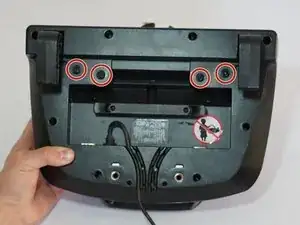
    • Nachdem du die vorbereitenden Schritte ausgeführt hast, drehe dein Lenkrad auf den Kopf.

    • Löse die vier etwas oberhalb der Mittellinie befindlichen Schrauben vom Boden des Geräts mit einem Kreuzschraubendreher PH1.

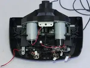
    • Drehe das Lenkrad wieder in die ursprüngliche Position und entferne das Motorgehäuse vom Rest des Geräts.

  15. ta5DsYr1cnKZe14M
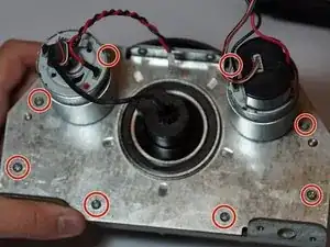
    • Löse die 8 Schrauben, die das metallene Motorgehäuse mit dem Kunststoffbauteil verbinden, mit einen Kreuzschlitz PH1.

    • Entferne das Motorgehäuse von dem Kunststoffbauteil.

    • In diesem Bild ist der optische Encoder mit dem Motor ganz rechts verbunden. Er hat ein schwarzes Kunststoffschutzgehäuse.

  16. Pt3EqUQDIXNcFMWg
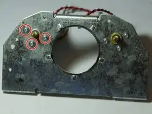
    • Drehe das Gerät und löse die 3 Schrauben, die den Motors ganz links mit der Metallplatte verbinden, mit einem PH1 Kreuzschlitzschraubendreher.

    • Entferne den Motor vollständig von der Metallplatte. Das wird es dir einfacher machen, den Motor zu bewegen um den Encoder auszutauschen.

  17. mnTynYtePPYsRSnB
    mnTynYtePPYsRSnB
    YhREFmurM3RPhZ1n
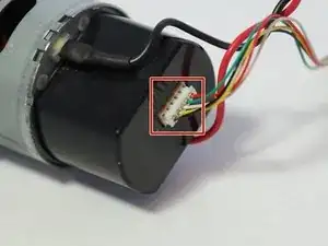
    • Ziehe den 5-poligen Stecker von der Rückseite des optischen Encoders.

    • Sei hier genauso vorsichtig wie bei all den anderen Steckern bisher: ziehe nicht an den Kabeln, sondern heble den Stecker heraus.

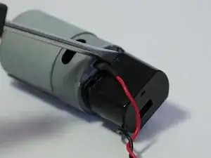
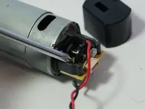
    • Entferne das Schutzgehäuse, indem du es mit einem Schlitzschraubendreher oder Hebelwerkzeug öffnest.

    bonsoir ou acheter les conecteur blanc avec les 5 fils pour volant g27

    philippegontier30@free.fr -

    ou acheter les connecteur blanc avec les 5 fils de couleur du volant g27

    philippegontier30@free.fr -

  18. CTBhP1eigOuhUrkB
    • Löse die beiden silbernen Schrauben von der Unterseite des optischen Encoders mit einem PH0 Kreuzschlitzschraubendreher. Das wird die Platine vom Motor lösen und die neue kann eingesetzt werden.

    • Sei sehr vorsichtig und verbiege nicht die LED oder den schwarzen Sensor, die von der Platine herausragen. Wenn sie nicht sich nicht in einer Flucht befinden, wird sich dein Lenkrad nicht kalibrieren können und du wirst es schwer haben, beide Elemente wieder zusammenzubauen.

    my wheel wont calibrate and sometimes it spits out a “power surge on usb” error and my optical encoder is good, what do i do?

    Jackson Beers -

    I like this replacement. https://es.aliexpress.com/item/329959435...

    At first I didn't calibrate myself. I realised that it has to be fully inserted and satin with the end of the motorbike cylinder, as you can see in the seller's pictures. Then it did calibrate.

    Evaristo Rivieccio Vega -

  19. IVItp52pCnaFjsVT
    IVItp52pCnaFjsVT
    ybh1WMhfCDkDE6rA
    nIaREUgYBXt6Y5ex
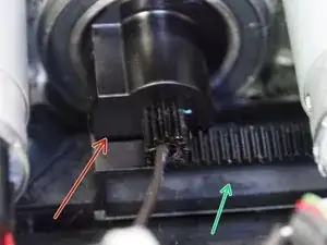
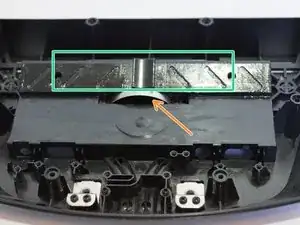
    • Stelle während dem Zusammenbau sicher, dass der Anschlag auf dem Zahnrad mit der Zahnstange ausgerichtet ist wie auf dem zweiten und dritten Bild.

    • Gehe auch sicher, dass der metallene halbkreisförmige Clip wieder ordentlich in der dazugehörigen Aufnahme sitzt.

    • Nachdem du den metallenen Clip wieder in die Aufnahme gesteckt hast, setze das Zahnrad wieder auf den Clip und auf die Zahnstange.

    Thank you ! ! ! !

    Patrick Ebensberger -

Abschluss

Befolge die Anleitung in umgekehrter Reihenfolge, um das Gerät wieder zusammenzubauen.

Grant Blake

Mitglied seit: 21/04/15

1554 Reputation

29 Kommentare

Where can you get the encoder to replace it?

invertig0 -

Hello and thanks for the guide. I understand this might be off topic, but would you happen to know the pinout of the7-pin connector in step 5? There is no label on the pins. Thanks in advance for your time.

Georgios Arkouzis -

Very much appreciate your assistance & time putting this together. I Chose the expoxy route. My wheel IS BACK!

Dave -
Are you sure about Step 19 alignment. Some other guy with G25 says it has to be dead centre alligned otherwise you get blinking lights.And that's exactly what happens to me.

robertleskovsek -

hi! i reassembled mine positioning it all the way to the right, and i have blinking power light and my wheel do not calibrate. what do you mean by dead centre aligned? i have to assemble it back together in center position, is that it?

felipezerobala -

Hey, really big thanks for this guide! I opened my wheel and found the optical encoder broken as foreseen. Just bought the brass version, but for the first instance I fixed the encoder by wrapping some thin tape around the edges and cut off the rest. worked well, but is not meant for a long time use.

As I managed to make this fault, please add a hint that when rearranging the wheel (reverse step 1+2 the thin wheel button wires love to slip close to the bottom left and right screwholes with the risk to be squezzed between wheel and wheel hub. Now I have repaired the wheel function and wrecked the upper left button function :-)

fulgorth -

Gracias a esta guía he podido reparar el volante G27. Muchas gracias.

urrielu -

You can buy a printed version here: https://www.shapeways.com/product/4FDSWS...

It worked great for me, it shipped within a week and I'm using it now for over 2 years without any problems.

2 versions are sold: 30 and 60 slot encoder.

60 slot is for G25 and early G27 later G27 wheels use the 30 slot version.

RacingVictim -

The three hub screws in step 6 refused to go all the way back in, and one of them stripped completely. If this happens to you, you can get shorter screws here to replace those very long screws - https://www.amazon.com/gp/product/B01MFA...

Obviously the screws being shorter means the wheel isn't as strongly attached to the base in this direction, so if you have to do this remember not to put unnecessary stress on these screws by pulling the wheel straight off the base.

Also the best replacement in terms of longevity for the encoder disk is the brass ones that you can order here, but shipping takes quite a while - http://cmlaserservice.com/index.html

I tried to 3D print one myself but it didn't work.

SouthernPotato -

Hello, i repaired the old optical encoder. Now when i connect my wheel to PC the calibration works. But then PC doesn't "read" when im stearing. The other buttons are ok. Please help me what to do. Thanks

Tom Bubok -

can you please share me the motor specifications?

Gokulraj S -

Is this questin for me?

Tom Bubok -

yeah ! I need this motor specifications :)

Gokulraj S -

Repaired with this guide, thanks.

For the repair of the optical encoder I used a washer.

smigolxp -

not encoder?? Washer??

Il Vloggatore -

is it work sameway??

Il Vloggatore -

I user a washer to repair the broken optical encoder.

smigolxp -

Excellent guide and thanks for the publication and your help !!!

Luca Ragno -

!!!!Took me a white 2FIX it but!!! LISTEN! !!If Your wheel aiant straight in center with good or new encoder TRY first in windows controllers menu .Wherę IT shows controler. Devices while pointing at your g25,7dfgt Device :Press Ctr+shift and right Mouse to engage wheel calibration. Thank you and You Welcome ;)

laikros -

Hi everyone. You can buy a replacement from there. Optical encoders available with 30 or 60 Slot. For 30 Slot check out this https://www.ebay.com/itm/264059488231 and for 60 Slot check out this https://www.ebay.com/itm/264059495927

Mister -

Also I have managed to change the encoder without disassembling the mainboard and bearing housing. Just remove the motor encoder cover and change the encoder. The same way worked on Driving Force GT

Mister -

Where can I order the optical IR sensor? I’m not getting my drive on without one …

DieCalmerThanASuicideBomber -

If someone tries do do this: Do not do step 9 to 16. It’s completely unnecessary and will just make it harder to assemble again. You can remove the cable and casing as described in step 17 just fine with some fiddling.

If you disassemble it completely as shown in this guide you will have to align the stop gear to the track again (step 19), which just doesn’t work well by visual estimate alone.

Viking Dinosaurs -

Hello

I changed my optical wheel, but after that my g27 doesn’t calibrate : power led is blinking, but the wheel doesn’t make its calibration process as the wheel is not moving… After three attempts, power led is blinking fast and that’s all.

I made a video of this problem : https://youtu.be/hihREK_QC1Q

I thought my optical wheel was too low (or too high) on the engin axis, so I tried to change its position but no effect.

If you have any idea…

Sylvain Jn -

I had the same issue. If you have a 3d-printed optical wheel replacement make sure to completely cover it with black marker. It has to be all the way black otherwise light can shine through the spokes and the encoder sends an error which results in the issue you’re having.

So even if it looks black.. just try again with the black marker..

Don H -

how many slot encoder do i need?

Nico Rosella -

Step 15 and 16 can be skipped! You can keep the motors attached to the frame to open up and replace the encoder wheel. (I just did it like that and that works fine)

Don H -

Good day sir

I have lost the 5 pin adapter

Please help me i am unable to find 5-pin adapter for encoder part online

I want to purchase it

DeadShoT World -

Hey,

I switched the encoder on my g27 with a brass one yet I'm facing another issue. With the old broken encoder, it only calibrated to the right. With the new one, It calibrates all the way from right to left but it doesn't come back to the center. Then it repeats the process 3 times but nothing happens. What could be the issue?

I've read people saying that I need to readjust the black plastic to the center on step 19.. any ideas?

Hannod -