Einleitung

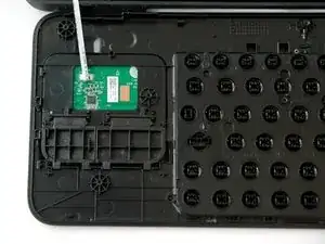
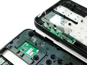
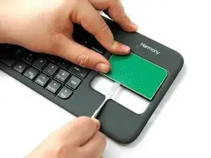
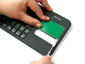
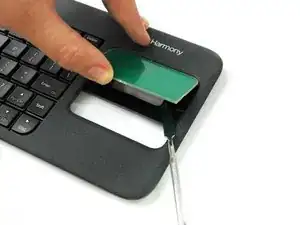
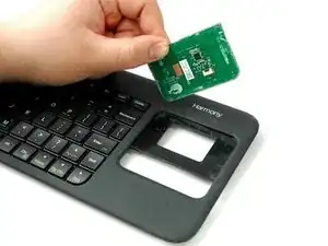
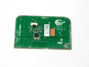
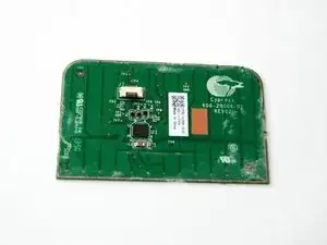
This guide will teach you to remove and replace the Logitech Harmony Smart Keyboard's Touchpad PCB.

The printed circuit board (PCB) mechanically assists and electrically connects electronic parts using conductive tracks, pads and other components. The PCB appears in the form of a thin, copper board.

  1. yeFWtiLBjSocyENG
    yeFWtiLBjSocyENG
    3BwD5hli2x1iLHhH
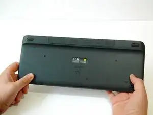
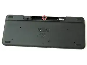
    • Turn keyboard over to the backside.

  2. bkilisV2dQGEFneF
    bkilisV2dQGEFneF
    L4Q6NyWEELcmN3MN
    ZsF2eLBUFaQNrbng
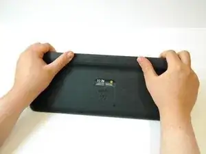
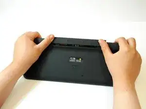
    • Press and slide up on the upper battery latch, using both thumbs.

  3. JgKfbQkckWndfV33
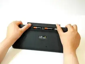
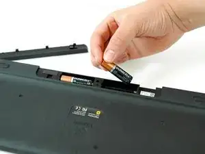
    • Remove the two AA batteries and set them aside.

  4. lqVPdDa2PXLNpiSU
    lqVPdDa2PXLNpiSU
    MwoTmVWnwIVdSHsw
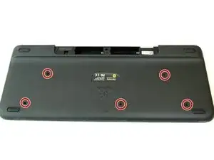
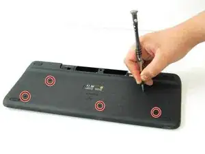
    • Unscrew all five 4.0 mm screws, using Phillips #1 screwdriver.

  5. MXrNtLXF3pKjVfQD
    MXrNtLXF3pKjVfQD
    iFygMbZQXpbCGdIX
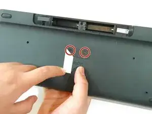
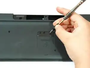
    • Peel off the center sticker to reveal two hidden 4.0 mm screws.

    • Unscrew these two screws with a Phillips #1 screwdriver.

  6. BFMJEZKGEgMUHwNF
    BFMJEZKGEgMUHwNF
    cllVdhlf45PBQTUt
    dT3NWxDTPZZxKbtX
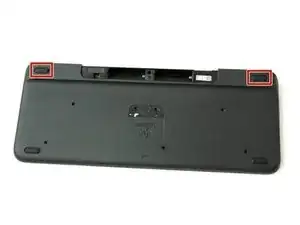
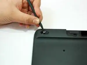
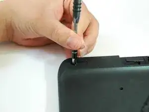
    • Lift both top left and top right rubber stickers halfway, using the sharp end of the plastic spudger.

    • Unscrew a total of two 4.0 mm screws, under the rubber stickers, using a Phillips #1 screwdriver.

  7. qhQFV4c2R6AZctUI
    qhQFV4c2R6AZctUI
    tvNV5yDa4AMypJFc
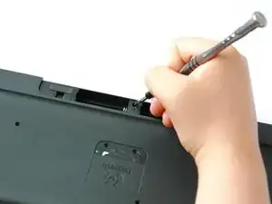
    • Unscrew the top center 4.0 mm screw, in the battery compartment, using the Phillips #1 screwdriver.

    • Now, you should have a total of ten 4.0 mm screws set aside.

  8. QvfEWbEEhCQ3RRP5
    QvfEWbEEhCQ3RRP5
    1AePc6T3aahPEOTZ
    2AJSDA35Ir3ZbWLD
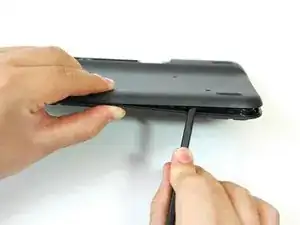
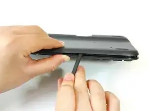
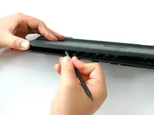
    • Wedge the flat end of the spudger between the back panel and front panel.

    • Slide the flat end of the spudger from right to left to pry the two panels apart.

  9. cDZ4OUrr5gyGT1PT
    cDZ4OUrr5gyGT1PT
    XIY3ovvr4Ts4MCef
    DY4UKtsBnNFgW1aW
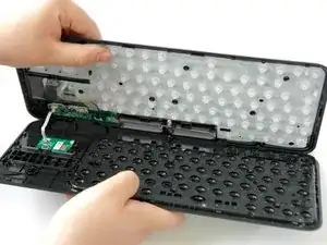
    • Separate the back panel from the front panel completely, using both hands.

    • A white ribbon flex cable will remain connected to both panels.

    • Pull the panels apart slowly and gently, or the white ribbon flex cable may be unsafely removed.

  10. JnoTXwZOBG3XRkDA
    JnoTXwZOBG3XRkDA
    2hZqEKwTynAMu5XY
    XWJMHxTPyuQCCCg1
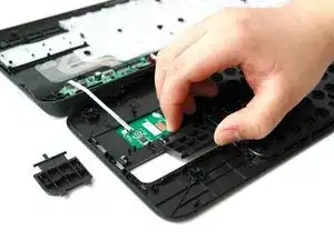
    • Lift up and pull off the track pad’s left and right clickers.

    • Use caution while lifting, lift slowly with slight pressure.

  11. 3MZ2SoxTCvcnSyqJ
    3MZ2SoxTCvcnSyqJ
    nLNY2vuAALe3XGcj
    rPiHt2EOUWDNpQnp
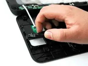
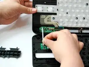
    • Grip the lower end of the ribbon flex cable (white band) using your thumb and index finger.

    • Then slide the strip out toward yourself in a scooping motion.

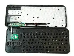
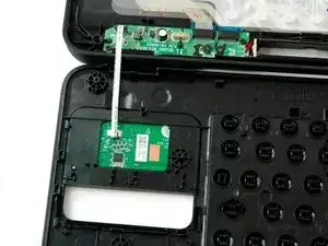
    • Now, you should have two completely separated panel pieces.

  12. SkoWSP1mTMZ4vX1Z
    • Flip the front panel over so the front side faces up, and rotate so the keys appear upside down.

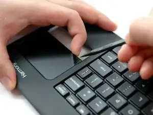
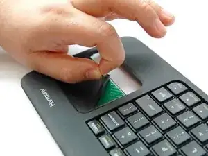
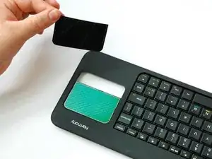
    • Lift the upper-right corner of the sensor sticker using the sharp end of the spudger and your index finger.

  13. JBtEBHsmIX2FVovS
    JBtEBHsmIX2FVovS
    SEOlUrN2Wyl6wfOt
    JBp5Rfolks3PIJ2y
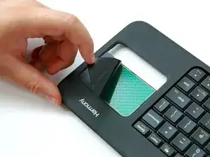
    • Peel the sticker off by pinching the sticker corner using your index finger and thumb.

  14. oCoknXcT2UXGhZgs
    oCoknXcT2UXGhZgs
    JFElVCLDJvZ2rMpe
    • Rotate the front panel around so the keys appear right-side up.

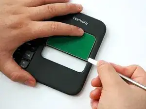
    • Wedge the flat-head metal spudger under the PCB's bottom-right corner.

    • Wedge and slide the spudger along the right side to reach the upper-right corner.

  15. AXXhP1xxF3RnPgpG
    AXXhP1xxF3RnPgpG
    LlDbVfKlOogYyiGC
    2IAcTRyKyIHyYDds
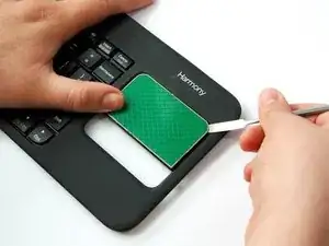
    • Wedge the flat-head metal spudger under the PCB's bottom-left corner.

    • Wedge and slide the spudger along the bottom side to reach the bottom-right corner.

  16. jTpDUnWgNtARkSSB
    jTpDUnWgNtARkSSB
    QZqExKG4NPJpmgDE
    IHunxdOugOBeVd4Q
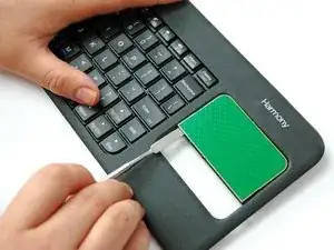
    • Slide and nudge the spudger upward underneath the PCB.

    • Wiggle and lift up the PCB with your thumb as you nudge the spudger up to release the PCB.

Abschluss

To reassemble your device, follow these instructions in reverse order.
Edwin Aguilar

Mitglied seit: 11/09/17

137 Reputation

0 Kommentare