Einleitung

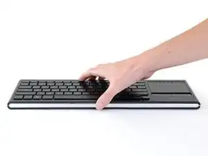
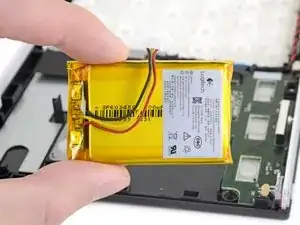
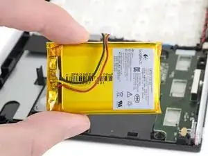
Follow this guide to remove and replace the battery on a Logitech K830 keyboard.

For your safety, discharge the battery below 25% before disassembling your keyboard. This reduces the risk of a dangerous thermal event if the battery is accidentally damaged during the repair. If your battery is swollen, take appropriate precautions.

  1. 6urkIKPa2fPW1ddo
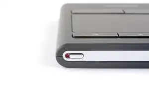
    • Flip the keyboard's power switch into the OFF position.

    • A red indicator is visible beneath the switch when it's in the OFF position.

  2. W1lxwjJDKCsNwq34
    W1lxwjJDKCsNwq34
    XVfMiBHh5E6OxHbW
    FPFypbIN3NXZqTMD
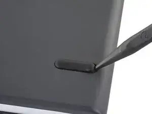
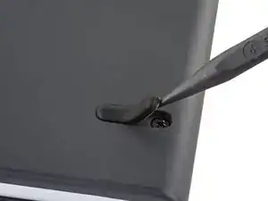
    • Insert the pointed end of a spudger under the edge of one of the feet.

    • Push the spudger underneath the foot and pry up to release its adhesive.

    • The foot should come away from the keyboard without much force. Pry slowly to avoid tearing the foot.

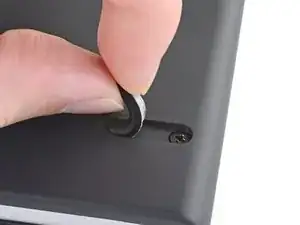
    • Once you can grip the foot with your fingers, peel it up and away from the keyboard to remove it.

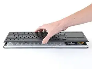
    • Repeat this step for the remaining three feet.

  3. RY3iVG6FAv32jFot
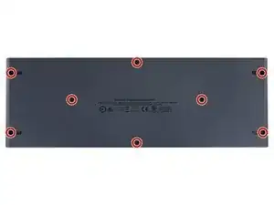
    • Use a Phillips screwdriver to remove the eight 6.8 mm-long screws securing the upper case to the lower case.

  4. ykPSITx3bYgAjc4Q
    ykPSITx3bYgAjc4Q
    ifAEH12sPuejHejI
    • The upper case is secured to the lower case by clips on every side of the keyboard. In the next steps, you'll release the clips on each side.

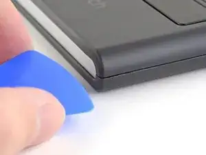
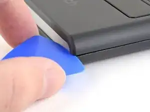
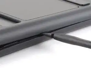
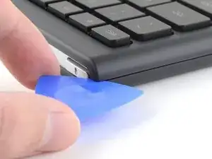
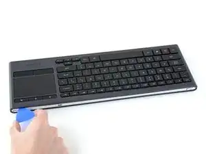
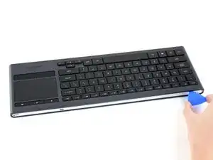
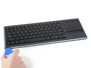
    • Insert an opening pick about 2 mm into the gap between the upper case and lower case at the bottom-right corner of the keyboard.

    • This creates a gap large enough to insert the flat end of a spudger.

  5. p4edmSK5bTUH61AL
    p4edmSK5bTUH61AL
    3bWKSqyFUMT1fM3g
    ibZQGCISpKNSeZGs
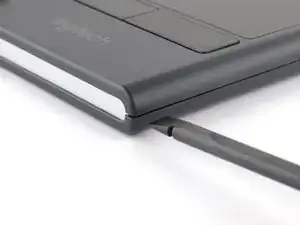
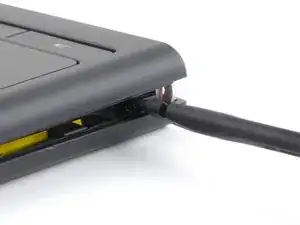
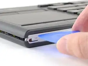
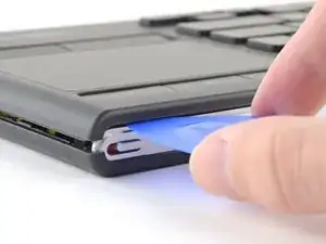
    • Don't insert the spudger more than 2 mm into the keyboard or you may damage internal components.

    • The internal battery is located near the right edge of the keyboard. Take care not to puncture or bend the battery with your spudger—a punctured or bent battery may leak dangerous chemicals or cause a thermal event.

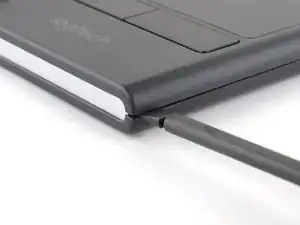
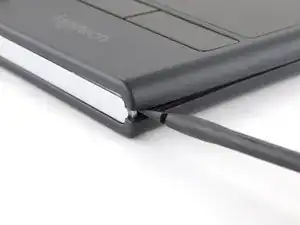
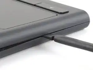
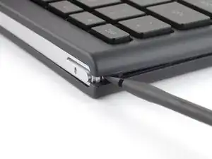
    • Insert the flat end of a spudger about 2 mm into the gap between the upper case and lower case in the bottom right corner of the keyboard.

    • Rotate the spudger clockwise to release the first clip.

  6. RjTFuxXbMKKXf2JZ
    RjTFuxXbMKKXf2JZ
    fXTPcxvAfg1pZIjQ
    Y1W6QfSwRQFDXbj1
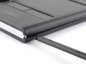
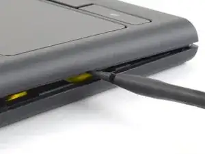
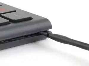
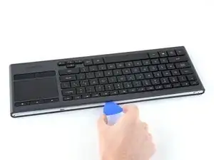
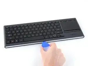
    • Move the spudger about 3 cm along the keyboard's edge toward the volume buttons.

    • Rotate the spudger clockwise to release the next clip.

  7. l2ZUtHSOnEjL5VpJ
    l2ZUtHSOnEjL5VpJ
    BOMf42ZBJIbmaEXg
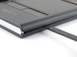
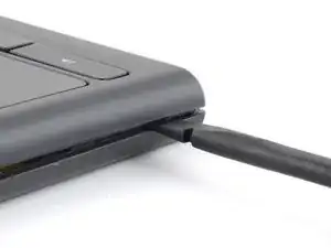
    • Move the spudger about 3 cm along the keyboard's edge toward the volume buttons.

    • The spudger should now be about in the middle of the right edge of the keyboard.

    • Rotate the spudger clockwise to release the next clip.

  8. 4csNH1qQwQ5uESK2
    4csNH1qQwQ5uESK2
    XARitBy4NN3QSqFL
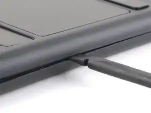
    • Move the spudger another 3 cm toward the volume buttons and repeat the previous step.

  9. niZ2QwUKfxbXKwLA
    niZ2QwUKfxbXKwLA
    QxdnRkLZWj2pIrVM
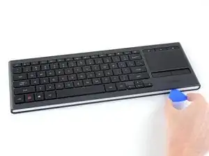
    • Move the spudger another 3 cm toward the volume buttons and repeat the previous step.

    • The spudger should now be at the top-right of the keyboard.

  10. rPsZnLxYqgBS2IPf
    rPsZnLxYqgBS2IPf
    OEDIkR6fKjiSrVKA
    GlFAyWTHOnB4TBIf
    • Repeat the clip release procedure for the left edge of the keyboard.

  11. LeEMeCLNpMN2eDKH
    LeEMeCLNpMN2eDKH
    sKcFLKtYucfYA4cb
    • Don't insert the opening pick more than 2 mm into the case or you may damage internal components.

    • Insert an opening pick about 2 mm into the gap between the upper case and the gray support bar closest to the volume buttons.

  12. 6XBhlAUbDGB4GBFG
    6XBhlAUbDGB4GBFG
    lCn53amBU6HLNFXr
    YXySbqTKTEYmSdN4
    • Slide the opening pick across the entire length of the keyboard to release the clips on the top edge.

  13. bELRmIqTiXCqvpEN
    bELRmIqTiXCqvpEN
    4iccFNhESAMsTeN5
    RZQOuGPTrDbtQONS
    • Repeat the last step for the bottom of the keyboard.

  14. JPR2BQKAOZQVyfAF
    JPR2BQKAOZQVyfAF
    Y6fyEobQiGnhUHWj
    TBdLsuFQMWu2Pl3T
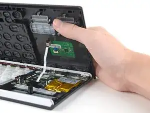
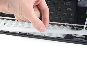
    • Don't try to remove the upper case completely—it's still attached to the lower case by a delicate interconnect cable.

    • Lift the upper case up by about 2 cm.

    • If the upper case doesn't lift completely off of the lower case, repeat the clip release procedure for the stuck area.

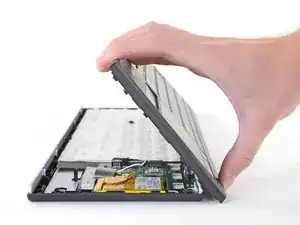
    • Tilt the upper case about 45 degrees so that the keycap letters are upside-down.

    • Keep the upper case as close to the lower case as possible to avoid straining the interconnect cable.

  15. CY1sfGPLMfDApX6O
    CY1sfGPLMfDApX6O
    BXWSDLsnON5EZYD6
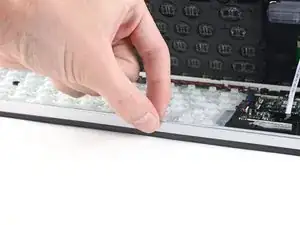
    • Place the top edge of the upper case on your work surface as close to the lower case as possible.

    • Hold the upper case at about 45 degrees to avoid straining the interconnect cable.

  16. MGyQI6OnRTGLRwBL
    MGyQI6OnRTGLRwBL
    vc6RAuaRqfTsrsJo
    • If the gray support bars fall out during this repair, place them back into their slots with their notches facing upward.

  17. YGUumNA6vDShXBsA
    YGUumNA6vDShXBsA
    gNoWFXNfUCOZ654D
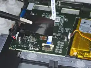
    • Remove the black tape covering the interconnect cable connector.

    • Set this tape aside. During reassembly, place the tape back into its original position on the motherboard. Be careful not to damage any of the surface-mounted components.

  18. oTMklrWTmUfDUGeh
    oTMklrWTmUfDUGeh
    GGH3qunIWKKyiaFd
    Rrr1XNDn62KvkyjF
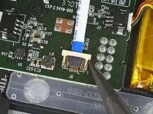
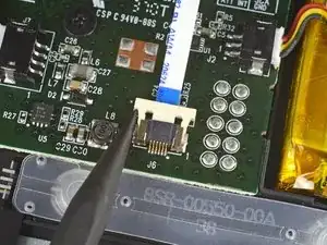
    • Use the pointed end of a spudger to push the interconnect cable connector's locking tab toward the cable.

    • The connector is unlocked when the locking tab lines up with the white rectangle on the motherboard.

  19. 3G6PO4jhP4k6TFsL
    3G6PO4jhP4k6TFsL
    rLhW1Sd4MHYUpURp
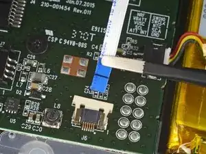
    • Use a pair of blunt tweezers to grip the interconnect cable by the blue section close to the connector.

    • Pull the interconnect cable out of its connector in the direction of the cable.

    • During reassembly, follow these steps to reconnect the interconnect cable:

    • Make sure the locking tab is in the unlocked position.

    • Insert the ribbon cable so that the black line on the cable lines up with the white rectangle's edge closest to the cable.

    • Use your fingernail to move the locking tab into the locked position.

  20. ejFg2HPR1bHC5XTV
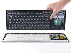
    • Remove the upper case from the lower case.

  21. 1FU3d1eeER2T6W3b
    1FU3d1eeER2T6W3b
    MyyHMIMke5GGqVYe
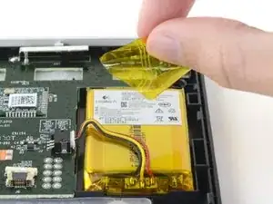
    • Remove the yellow tape covering the battery cables.

    • Set this tape aside. During reassembly, place the tape back into its original position covering the cables on the battery.

  22. JWJq6djlkL4MusIh
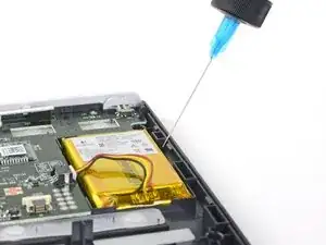
    • Take care not to puncture or bend the battery—a punctured or bent battery may leak dangerous chemicals or cause a thermal event.

    • Apply a few drops of high-concentration (90% or higher) isopropyl alcohol under the battery edge opposite the battery connector.

    • Wait one minute for the isopropyl alcohol to weaken the adhesive under the battery.

  23. DyYVPmqt5reSsXCT
    DyYVPmqt5reSsXCT
    KB3fZaSuqLMQGJsm
    qy2vkllJgFLvbIXF
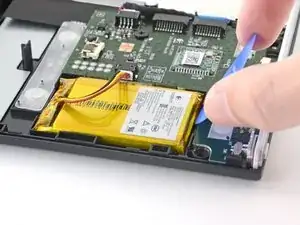
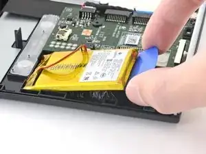
    • Slowly insert the tip of an opening pick under the top edge of the battery.

    • Make sure the opening pick is sliding under the battery and not pushing into the battery's side.

    • If the opening pick isn't sliding under the battery, apply more isopropyl alcohol and try again.

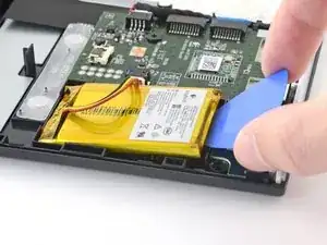
    • Push about half of the opening pick under the battery while slowly lifting up.

  24. wgdnkrLNacDOIX1I
    wgdnkrLNacDOIX1I
    sKZwAkkTLZ1vKM4m
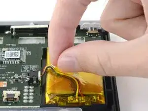
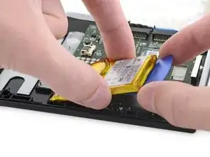
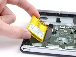
    • Use your fingers to lift the battery about 1 cm above the battery recess.

    • Take care not to strain the battery cables while handling the battery or you may damage the battery connector socket.

  25. GqCuciETZ3UdYi1x
    GqCuciETZ3UdYi1x
    AnOfEjH5PyhASi45
    RHmoLIGRmjPcyRLT
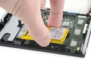
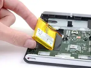
    • Rotate the battery 45 degrees so that the edge closest to the battery connector rests in the battery recess about 1 cm from the connector.

    • Place two fingers under the bottom side of the battery to support it.

  26. mGAB2CNeMmGBL2l1
    mGAB2CNeMmGBL2l1
    HqfUIw3xKrsRZ21M
    6PiQDEEwUQEHsATR
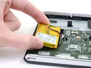
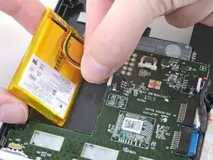
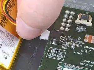
    • While supporting the battery, disconnect the battery by pulling on the three cables as close to the connector as possible.

    • If the battery connector doesn't easily come out of the socket, gently rock it back and forth to "walk" it out of the socket.

    • During reassembly, make sure the battery connector is oriented correctly. The black cable should be on the side closest to the ten solder points on the motherboard.

  27. UQhRlOBaXdtYdYSM
    • Remove the battery from the keyboard.

    • If there's any alcohol solution remaining in the keyboard, carefully wipe it off with a coffee filter or allow it to air dry before installing your battery.

    • Do not reuse the battery after it has been removed, as doing so is a potential safety hazard. Replace it with a new battery.

    • During reassembly, follow this guide if you are using a pre-cut adhesive card to secure the battery.

Abschluss

Compare your new replacement part to the original part—you may need to transfer remaining components or remove adhesive backings from the new part before installing.

To reassemble your device, follow these instructions in reverse order.

Take your e-waste to an R2 or e-Stewards certified recycler.

Repair didn’t go as planned? Try some basic troubleshooting, or ask our Logitech K830 Answers community for help.
Kyle Smith

Mitglied seit: 01/02/21

35834 Reputation

0 Kommentare