Einleitung

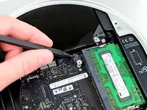
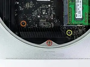
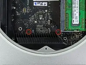
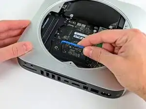
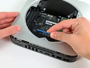
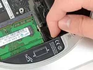
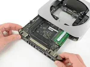
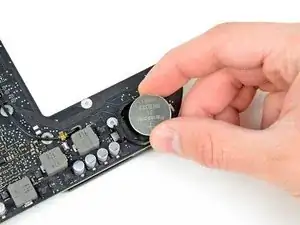
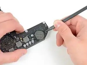
Hier wird der Austausch der PRAM Batterie gezeigt.

  1. p5voHV2WbSJTcHTV
    p5voHV2WbSJTcHTV
    t2lX4AlfsU3MwcGL
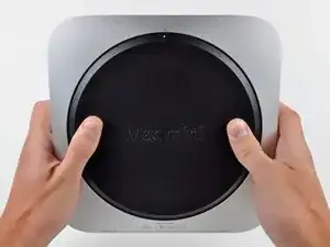
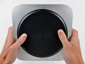
    • Mit den Daumen in die Vertiefungen der Bodenplatte drücken.

    • Die Bodenplatte jetzt gegen den Uhrzeigersinn drehen, bis der weiße Punkt mit der Markierung auf dem Außengehäuse übereinstimmt.

    • Während des Drehens sollte man nicht zu fest drücken.

    This took a lot of force on my Mac mini. A lot.

    nh3 -

    I agree. It took a crap ton of force from my thumbs to twist the bottom off.

    sleeve -

    I accidentally broke the little things that hold the cover to the case. Is there a cheap replacement to the cover? Those clips are held onto it very weakly.

    Jacob Halton -

    Don't just use your thumbs... Use your whole palm to twist it, with maybe a thumb in one of the recesses, applying slight downward pressure.

    markbart -

    Wish I would have read this comment before I did it!

    I found that what markbart said works best. one palm one thumb (and my knees) My thumbs would do it. It was a bit at a time.

    Same difficulty getting it back on.

    Would be handy if this (difficulty) was mentioned in the guide

    Also would be nice to mention the safe practice of pressing the power button for a few seconds after disconnected to rid the system of any residual power, working in a clean static free environment & they say on the crucial website to touch a metal surface of the machine before touching the RAM

    Nancy -

    I think it depends, I have seen some that are very difficult to open and some super easy. But I see them everyday. I wish there was a tool that fit in the holes.

    Justin Weathersbee -

    When seating the bottom RAM chip you may have to apply a little extra side force to get it to seat properly. I put in the new RAM and just got a beeping sound upon starting. I then put the old RAM back in and got the same result.

    Here is the solution I found on the Apple discussion board.

    "Take a small flat head screwdriver and after you put the memory in slot 0, put the screwdriver between the top of the mac mini and the memory then turn the screwdriver a little to exert pressure on the memory into the slot. Do it on both sides of the memory."

    This worked for me.

    littlemas2 -

    I remember this when I was changing my memory ... I realized (after opening) that more you push, more force it take to open the cover. As you push down you force the cover "to rub" the casing and possibly other things inside. If you "lightly" hold the cover it comes right off ... Remember: less is more! :-)

    Have fun!

    Radek -

    We found it hard to use the thumbs but if you put the casing on a carpet and one person is holding the case while the other is using his palm of one hand to turn the cover it comes off quite smoothly and without much downward pressure.

    Alexander -

    If you're upgrading to an SSD, before you even take this first step, I'd recommend putting the SSD into an external drive case, using USB and format the SSD first before trying to swap your existing hard drive or implementing a fusion drive. The external drive case will come in handy later so you can use the old drive as extra storage anyhow.

    Once that SSD is internal, the Mac errors out during the formatting process. Once it was formatted externally, then installed inside the Mac again, there was no problem.

    Orange Girl -

    The first time I did this it hurt! The second time my mac mini 2012 had been running so was warm. VERY EASY WHEN WARM. No fun when cool!

    Nancy -

    Forget about those 2 circle indents. if you consider the 2 marked dots (open and close) as position 12 o’clock, place your thumbs at 11 and 1 o’clock on the outer rim of the cover and rotate from that position.

    juicer52 -

    No way was I getting the back off. So I made a tool. Took a large wrench longer than the Mac mini. Superglued 2 rubber feet on the wrench at the same location as the thumb indents. Put the Mac on the ground, between my knees and used my body weight to turn the cover. Worked like a charm.

    Mark -

  2. OHeH6POHN2YreiPQ
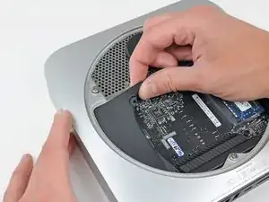
    • Den Mini leicht kippen, damit sich die Bodenplatte vom Gehäuse löst.

    • Bodenplatte entfernen und beiseite legen.

    I have a late 2012 Mac mini, but it must be an earlier version than this late 2012 Mac mini in this description, because removing the hard drive is much more complicated than described here. Please see this YouTube video if you have trouble removing your hard drive with these directions. https://www.youtube.com/watch?v=cvmuQIZP... There is a longer process you've got to go through. It can be done, it just takes much longer. (3-4 hours for me)

    sandyfacebook -

    This applied to me as well. The iFixit article was good and lots of helpful information in the comments but my mini was different and required more dismantling. The video sandyfacebook posted was very helpful in taking me the rest of the way. https://www.youtube.com/watch?v=cvmuQIZP...

    Erik Heerlein -

    My HDD replacement procedure took 2 jours of research, one night sleeping on it and 30 minutes to perform…

    Rene Girardin -

  3. VSBK45eaYv4AVsjx
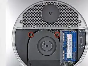
    • Entferne die beiden 11,3 mm T6 Torx Schrauben, die den Lüfter auf der Platine nahe der Funkantenne festhalten.

    On my mini, the fan has a 3rd screw on the bottom right of its housing just out of sight on the step 3 photo. I believe it was in the hole later referred to as the 26 mm T6 Torx standoff in step 14.

    benjamin -

    Remove a third screw at the opposite end of the fan near the DRAM

    Craig Foster -

    Not necessary to remove that screw at that point to get the fan out. It is only a post at that point.

    Remove it in step 14.

    Craig Reilly -

    I needed a T7 for this, and had to remove all three screws before I could take the fan out.

    mackrell -

    The fan has in fact, 3 screws that need to be removed before you can lift it out.

    FinnCrisp888 -

    That screw is a post at that point. I removed it at step 14.

    Craig Reilly -

    The 3rd screw needed a T5, for me.

    Martin Cleaver -

    All of mine have 3-T6 screws.

    Kadah Coba -

    I can't, for the life of me, get the left screw out of the cowling. Had to pull both out together. Now having a very hard time getting the cowling back in to replace the fan.

    Elvin Lucic -

    I can’t remove the left screw to separate the fan to the cooler. Impossible to put back the fan and the cooler.

    Jérôme Rosat -

    One of my fan screws don't come out, even though I keep trying to unscrew the screw. I tried a lot of things ranging from pulling the fan up to just trying to shake it out, please help me out with this

    cooldude20128 -

    Only two screws as stated above need to be removed but as people have found out, the one in the cowling can bind into the post below it and it’s the post below that unscrews instead. So you end up with the screw+the post+the fan all together as one. That assembly can be worked out, and then with two pairs of pliers the post and screw can be separated.

    The lower right T6 fan screw is a standoff (that also secures the logic board). This can be loosened and kept with the fan, or (since it is friction captured in a grommet on the fan), the fan can be lifted off, being careful not to dislodge the grommet.

    John -

    IMPORTANT: there’s a spring under the post which could go anywhere when the post comes out with the screw.

    John -

    Hi… Hi… Good. I have a query, I want to change my internal hard drive from my Mac Mini (mid) 2011, and my query is whether to remove the fan screws and other parts, which from what I was informed is the Torx T6 screwdriver. And my question is: to remove it I need a Torx T6 screwdriver with a hollow point or the Torx T6 with a flat tip will work for me. From what I have read, that the hollow point Torx are called Precision Torx or are identified with an "H" after the number in this case: "T6H". The same query is to remove the cover where the WiFi is, should I use a Torx T8 hollow point or does the flat point work for me? From now on I thank you get me out of this doubt, before doing something wrong. Thank you very much and greetings. Image (Augusto)

    Augusto -

    After having a look on YouTube at various methods I found it was not necessary to disconnect the fan or the antenna plate. I rotated the antenna plate out of the way and secured it with a piece of masking tape. I also found that I didn't have to move the logic board either. I lifted the HDD connector (gently) with a spludger . The original HDD came out easily once I managed to grip the plastic PCB cover (which isn't needed on the SSD) . Fitting the new SSD was easy using a masking tape 'handle' in the shape of an upside down 'T' . funnily enough the hardest part was getting the little plastic shroud on the left to sit nicely but even that was easy once I had used the masking tape 'handle' I'd used on the SSD. I always think the less you have to mess with the less chance of anything going wrong. Oh, and buy a antistatic wriststrap !

    Andy Dacosta -

  4. dWMVZSWPuIjtQJc5
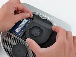
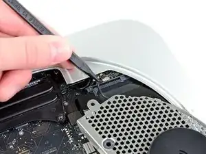
    • Hebe die Öse des Lüfters, die dem RAM am nächsten liegt, von dem am äußeren Gehäuse befestigten Abstandshalter ab.

    • Es ist nicht nötig den Abstandshalter zu entfernen, um den Lüfter herauszunehmen. Du musst den Lüfter lediglich so weit anheben, dass er sich herunternehmen lässt.

    Contrary to the instructions, I had to remove the fan screw

    radonr -

    Same for me, couldn't get it to move without feeling it was going to break so I just removed the screw.

    warrencox -

    Ditto re: standoff screw

    turkeyneck -

    Better to remove the 3rd bolt here, making it easier to remove the fan. It needs to be removed anyway in step 14.

    Bas Meijer -

    Mid 2011. I too had to remove the standoff screw. It seems to be a T5.

    lsbf -

    You will have to remove this screw in step 14, so why not now ;)

    mpalma -

    For me it was no prob to remove the fan just pulling carefully upwards.

    Timpetou -

    Mid 2011 Server, I had to remove the fan screw

    garzov -

    Mid 2011. The "yellow screw" from step 14 is captive in the fan and has to be removed in step 4.

    eric -

    Also it is much easier getting the fan correctly aligned on the stand of rubbery bit if you have the screw removed.

    aron -

    It’s no need to remove the screw

    fatych -

    I ended up removing the complete stand off post.

    Peter Stockwell -

    My whole fan connector just broke when reconnecting

    Vince lolol -

  5. MkJMSjgxs1gSljhR
    MkJMSjgxs1gSljhR
    BpvMCksHQ5qT5WS4
    oL6gTskCbqRZjWKm
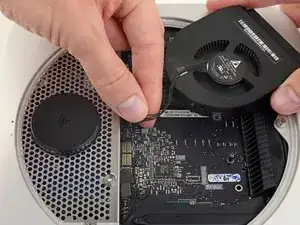
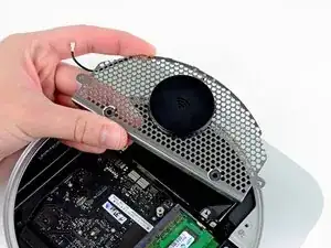
    • Nimm den Lüfter aus dem Mini heraus, sodass du ohne Probleme an die Anschlüsse kommst.

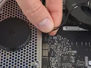
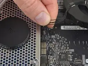
    • Fasse alle Lüfterkabel auf einmal und ziehe sie vorsichtig senkrecht nach oben, um den Lüfter vom Logic Board abzutrennen.

    • Heble nicht am Anschluss, du riskierst sonst, ihn vom Logic Board abzureißen.

    • Entferne den Lüfter.

    You actually don't need to disconnect the fan. You can just let it hang on the side while working. I accidentally killed my connector trying to pry it loose. It's being held together now by some tape, after spending hours trying to reconnect it and figuring out pin outs.

    Nick Michielsen -

    Did it just as Nick suggested, hang the assembly to the side.

    David Chan -

    Agreed. It is much better to leave the fan connected. The only thing you actually need to disconnect is the hard drive.

    ablack3 -

    Absolutely. just dangle it.

    Chuck Lin -

    110% agreed: you don’t have to remove the fan. Those wires are delicate, as is the connector. Just move it off to the side. Do the same for the antenna plate. The fewer connectors you touch, the fewer things you break!

    Chris Belanger -

    These instructions are used as a prerequisite for many other repairs where the fan simply has to be removed in order to continue. (For example, fan replacement.) I would not recommend leaving the fan dangling from the board during a repair, as that’s a hazard all by itself. If you insist on leaving the fan connected, secure it to the chassis with some masking tape to make it a little less dangerous.

    Jeff Suovanen -

    The fan has some slack cable on it. Once you have unscrewed the fan, you should see that the connecting cable is wrapped around two hooks. CAREFULLY move the cable around the hooks to free it. You can then move the fan to one side out of the way while you access the hard drive bay. On reassembly, thread the cable back around the hooks before screwing it back in.

    Ritchie Swann -

    Be careful to LIFT UP on the fan connector cable. Using a spudger tool helps here. I mistakenly thought that the connector would slide off the logic board and tried to remove the connector this way. I ended up lifting the connector off of the logic board, thus ruining my logic board and requiring a $350 logic board replacement at the genius bar. The second time I did a HD/SSD replacement, everything worked fine.

    Matthew Wagner -

    Yeah, I did the same thing by following someone elses "shortcut". Now I am going to shell out 289 for quad core i5 board, and a new fan BTW. . . . . . Oh well never a dull moment :) and it gets an upgrade as well!

    rob Stewart -

    That's probably the must tricky part of the replacement. I did the same thing, i just pull on my cables and the connector stays on the board. Tried many times to switch cables into but any order i try is not the good one.

    The avoid this, now, when i want to pull out my fan, i just use a plate screwdriver and lift up the connector. That's work perfectly.

    ayottepl -

    I've just pulled out the connector that's soldered to the logic board because I used a pry tool. Be careful at this point to just pull gently on the four cables that go to the fan.

    No Name -

    The CAUTION in step 13, "Make sure to pry up from beneath the wires and not underneath the socket," applies to this step as well, for removal of the fan wires.

    lsbf -

    I screwed it too... Not reading carefully enough, I accidentally removed the whole socket from the board. This happened with the IR connector too. When re-assembling the parts, the socket wouldn't stick to the board, now I know why. I don't want to buy a new logic board, because I can't afford one, so I'm trying to find someone to solder it. Seems hard to find someone able to repair logic boards these days. Hope I'll be successful, otherwise this is an expensive upgrade to my mac...

    Floffrob -

    Don't remove it with your fingers, use a tool for that. And underneath the wires!

    sebcthiebaud -

    Followed all the instructions, everything went well, but now my mini fan won't turn off. It starts as soon as I boot up. I've tried every fan control software out there, and nothing works; the fan just constantly runs. I was very careful when I disconnected/reconnected the fan cable, and it looks fine. What else can I do?

    Ben Dunkle -

    The problem is most likely a disconnected or damaged temperature sensor, I had this problem when reassembling a 2007 Mac mini. It can't read the temperature, so assumes the worst and sets the fan to maximum.

    patronics -

    I broke the fan wires from the connector plug. Impossible to repair. I have ordered a new fan. Is there a correct orientation to plugging in the new connector?

    ronhixson -

    For heavens sake please DON'T remove the fan. It's really really hard to reconnect it properly. And besides that you don't have to remove the Logic Board for just changing the HDD.

    Greg Kollmann -

    It’s very easy to reconnect if you know how. Position the connector over the socket as shown in the photo, and press it down. As long as it’s not upside-down or anything, you’re done in 5 seconds.

    Jeff Suovanen -

    Does anyone know how to solve the full RPM fan issue? My computer guy couldn't solve with fan control software

    J beneventi -

    I removed the fan and everything worked fine, but it’s good to know that it’s a “push-down“ connector, took me some time to relize that, all I needed to do was to press down the connector over the pins, see the picture for more details.

    Jan Igerud -

    SO glad I read these comments first.

    I changed the directions to read:

    “Use a Spudger to carefully pry the fan cable connector UP out of its socket on the logic board.“

    You guys DO know you can edit these, right?

    Brian -

    The direction you “ gently pull” to remove the connector is all important. You have to pull upwards, vertically away from the board. If you pull more downwards parallel to the board, you may end up wrecking the connector by pulling the wires out of it as I did. Fortunately the socket was okay so it was just a case of buying a $10 replacement fan (complete with new connector).

    David -

    DAGNABBIT! Broke it! Now I have a fan blowing on the open case while it’s operating. What can I use as a shield for dust but still allow for airflow?

    william8248 -

    OMG, please change this instruction to NOT remove the fan. What a nightmare trying to reseat it.

    Donald Braman -

    You need to position it over the socket as shown and press straight down. If it takes you more than 5-10 seconds, something’s wrong.

    Jeff Suovanen -

    really wish i would have seen these comments before I ripped out the fan from the logic board.

    frankie messinja -

    I missed the word UP and instead pulled the wires straight out, which ended up with me holding the wires but leaving the plug behind in the socket. I just ordered a replacement fan from ebay, since ifixit is out of the one in the correct amperage for this unit.

    I then edited the guide to capitalize and bold the word “UP” and hopefully that saves somebody else a bit of hassle.

    Any step with a lot of comments is one people have trouble with. It might be useful if ifixit were to make it more obvious we should read the comments, at least for those that have a lot of them. It would save a lot of people a lot of hassle.

    James Vasile -

    Just for emphasis on this point, I did exactly that - I ripped the fan connector right off of a perfectly good logic board. I used a plastic pry tool and was attempting to follow OWC video for replacing the drive. So beware! Trust me, it is not that hard to rip this thing off the board.

    Neal Sosdian -

    DO NOT REMOVE THE FAN.

    Put it to one side.

    Curtin Architecture -

    Here’s a video showing how this is done: https://youtu.be/KlR-RWtqzis

    glennbecker -

  6. Rd3TuDxXMVOSOXmI
    • Entferne die einzige 3,5 mm T6 Torx Schraube, mit der die Haube am Kühlkörper befestigt ist.

    in Step 6 — Cowling ; " Remove the single 3.5 mm T6 Torx screw securing the cowling to the heat sink", does it mean that it is the same T6 Torx screw for the cowling and the heat sink ?

    In fact at the end, I mess this T6 Torx screw !

    cegondaireun -

    Uhh I can't get this to go back in? Not sure what is going on...

    David Inman -

    Note that when you are replacing this cowling you are putting the screw back into what looks like another screw that holds the heat sink to the logic board. Disconcerting but correct.

    thrint -

    Thank you!

    I kept looking at that screw and wondering why I was trying to screw that screw into another screw.

    I've done removal and reinstalling a couple of days apart and I don't remember everything about what happened and where things came from. You're not wrong that it's disconcerting!

    Andrew K -

    Note That the arc of the cowling does not butt to the edge of the chassis. But slides in below it. Once the two screws on the heat sink are aligned with the cowling holes, it's good to go.

    imtimrob -

    used a T7 head to get this one out.

    patjmccarthy -

    Does this screw have a spring attached to it?

    martinknowsbest -

  7. RfnDauGTbLmaAXGJ
    • Hebe die Haube an der Seite an die dem Antennenblech am nächsten liegt.

    • Drehe sie vom Gehäuse weg und ziehe sie ab.

    Look very closely at how this is set. Take a photo. Because when I put mine back together it took 45 minutes just to get the fan and this cowling to fit in place next to each other.

    sandyfacebook -

    The cowling has a notch close to the midpoint of the flange that goes under the outer case, which slides onto a standoff screw attached to the logic board. I used a Sharpie marker to put one "alignment mark" on the inner edge of the outer case. I put another alignment mark from the midpoint of the cowling notch out onto the visible part of the cowling. This made it much easer to reassemble, especially since my standoff post provided a tight fit, which, when I did this the first time, felt like "it doesn't fit . . . again?" It also helped to insert the end of the cowling closest to the heat sink first, which acted as a "fulcrum" for the cowling to "click" onto the standoff post.

    Carrick -

    On reassembly, if you're having trouble lining up the cowling with the screw holes, you can try pulling the logic board out a tad and set the cowling in place. Just try not to damage the cowling or the inside of the outer case when sliding it back in!

    Drew -

    This is one of the few problems I had when reassembling because I didn’t realise at first that the cowling goes just under the lip of the outer case rather than just butting up against it; once done, it’s easy to line up the screw holes.

    eggs -

    Thank you Carrick!

    geoff.dunkak -

    I am working on a late 2012 Mac Mini (A1347) and there are two T6 screws on the cowling. On towards the WIFI as indicated, and another towards the back by the SD card slot.

    Roman Sturgis -

    this is for the mac mini 2011. for mac mini 2012, see here: Mac mini Late 2012 Repair

    Gray Greensheim -

  8. Mm3kYeoh1ZFnVVrN
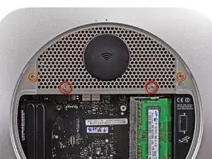
    • Entferne folgende Schrauben, die das Antennenblech am Mini festhalten:

    • Zwei 6,6 mm T8 Torx Schrauben

    • Zwei 5,0 mm T8 Torx Schrauben oder 2,0 mm Sechskantschrauben (beide Schraubendreher funktionieren)

    • Beachte beim Zusammenbau:

    • Es kann schwierig sein die Festplatte so zu platzieren, dass das Antennenblech richtig passt. Wenn die Schraubenlöcher nicht genau über denen der Festplatte sitzen kontrolliere, dass die beiden Stifte auf der Rückseite der Festplatte genau in den entsprechenden Löchern über dem Platz für die zweite Festplatte auf dem Gehäuse sitzen.

    • Die Antenne ist direkt an der Festplatte befestigt (rot markiert), daher kann es sein, dass sich beim Befestigen die Festplatte bewegt und das Verbindungskabel der Festlatte zur Platine lockert.

    When reassembling this aerial plate, it may take a very strong force to align the side lips with the screw bays. The circular edge on the body is meant to slot into the plate by less than 1mm. I followed the rule of thumb, which is, if it takes an unusual force, stop and think it out to avoid a disaster! Then, I hit on using a paper clip to get around this problem. Make a paper clip L-shaped to loop through a hole close to the edge of the plate, where the slotting is not deep enough. Gently lifting the paper clip, slide and push the aerial plate in place. This worked like a charm without using a strong force.

    al dente -

    Worked like a charm, saved my day!!!

    David -

    @Al Dente’s approach worked for me, but at first I didn’t understand what he meant. Basically the antenna mesh has a tongue and grove relationship with the mac mini shell; it is hard to see, but along the curved edge has a concave grove which needs to be widened. You can widen this concave grove with a paper clip and then it will fit perfectly.

    Ife Nkechukwu -

    Wow! I struggled with this for at least 1 1/2 hours. Then I tried this suggestion and it worked with ease and immediately. Genius suggestion. Thanks!!!

    Kbwood -

    My only real problem in the whole process was putting back the antenna plate. Couldn't get both side screws to align. Ended up leaving one out but might try the paper clip trick now

    andrewarwas -

    I had a similar experience, but when I realized the two 5.0mm T8 Torx screws were 2 of a set of 3 that also served to hold the cover on, I wasn't comfortable with only securing the cover with 2.

    UNSC Jon 117 -

    DO NOT BRUTE FORCE the reinstallation of the plate. In my case, the top lip of the antenna plate has a notch which aligns with the edge of the opening was preventing the perfect fit. All I did in my case was use the spudger to pry open the notch a little more to give me a little bit extra space so that edge of the aluminum enclosure fits into that notch on the top of the antenna plate. Hope that helps. :)

    chicosy -

    I did this too. Worked like a charm.

    ablack3 -

    Thanks for the tip: I did the same thing and it worked like a charm

    Zitoune7 -

    I was installing an SSD in my mini and when I got to this step, an issue came up. The two 6.6mm screws on the antenna plate screw into one side of, and secure, the hard drive. The problem was the SSD was thinner than the original hard drive, so when I tried to reassemble, the hard drive sat too low for the screws to reach it.

    Here's how I got around the problem. I loosely attached the antenna plate to the hard drive, leaving plenty of wiggle room between the plate and the drive. I also left the two stand off screws on the logic board off to give me more wiggle room there.

    With the SSD attached to the antenna plate, I carefully connected and stowed the Bluetooth cable. Using the antenna plate as a handle, I was able to guide the SSD into the hard drive mount. Once in place, I tightened the 6.6mm screws more, which raised the SSD to the proper level.

    After insuring that the screws all lined up, I installed and tightened the logic board, then the other antenna plate screws.

    yourgenius -

    I was able to achieve the same result with an slim SSD disk by simply turning the computer around with the access hole down so that gravity would pull the SSD towards the antenna plate.

    Mikael -

    I attached the SSD to the antenna plate FIRST. Then I connected the RF and the HD connectors during the antenna plate installation.

    Robert Reid -

    After trying these suggestions with a thinner SSD and couldn't get anywhere I used a bent paper clip, L-shaped, to act as a hook. One end I was able to simply hook under the drive and pull it up to install that ends screw loosely. The opposite end I inserted the paper clip through the antenna grate, again pulled up on the drive, installed the screw and carefully pulled the paper clip out.

    Tony Visconti -

    I used a spudger to lift the SSD so that it reached the screws. Not the best solution as the spudger applied some force on the board but it worked.

    vlada -

    The SSD was obviously thinner than the old HDD it was replacing so the screws didn’t contact the threads.

    As “Mikael”^^ said… flipped it upside down and it worked a treat!!! Cheers dude :-)

    Also the paperclip trick came to the rescue to get the antenna plate back on, couldn’t quite get it to sit correctly otherwise!

    Thanks all :-)

    Oliver Fox -

    The "engineering tolerances" are definitely tight for the AirPort antenna plate. I would recommend trying to replace it as soon as it's removed for the first time, in order to work out the (precise) alignment of it.

    Nothing I tried (including the suggestions here) seemed to help me during reassembly. No matter what I tried, I couldn't get the holes for the two 5.0mm T8 screws to line up. Eventually, I had to resort to CAREFULLY and SLIGHTLY re-bending the curved edge of the antenna plate.

    UNSC Jon 117 -

    REATTACHING grate - al dente's trick helped me.

    The tiny perforations on the grate rest ON TOP of the lip of the case, while the remainder of the grate slides UNDER the lip. It is very hard to see - I used a magnifying glass.

    To get it into place, create a tiny hook on the end of a paperclip. Moving along the edge of the grate, lift a perforation with the hook to help it slip into place. Keep moving along the edge until entire grate is shifted into place.

    Chris 1000 -

    I had several 2-terminal connectors that went to what appeared to be temperature sensors on several components including the hard disk and optical drive. I accidentally pulled the wires out of one of these connectors. Lucky for me, they came out clean and I was able to just re-insert them into the connector

    Kyle Jurick -

    On a Mini bought Jan 2014, Red screws were T-9 and orange were 2mm Hex, T-8 didn't work in either one. T-9 didn't work in orange.

    michael -

    As everyone else has noted during re-assembly, seating the antenna plate is tricky. For me, what ended up working was to attach the hard drive screws first. After this, with just a little wiggling of the plate, the 2 5mm screw holes lined up perfectly.

    jonathansturges -

    Aligning the drive holes with the ones on the antenna grate was easy – just take the pointy end of the spudger. Also, for getting the circular part of the grate set correctly, I had to bend down the outermost part a tiny little bit and then used curved tweezers to lift the grate once it was near its final position to get it slide in the last millimeter. Frustrating at first, but it worked after a few tries.

    Julian -

    Has anyone had any trouble getting the two 5.0mm screws back in place? I can't seem to get them in, as they just keep on turning. I thought the thread may have been damaged but I then removed the plate and could screw them in position okay. It seems the depth of the plate is causing the screws to not go down far enough. I've had to leave these off at the moment (obviously not great as this means the bottom cover is loose. Any ideas?

    alan -

    I had the same problem but only on one of the two screws. Then I realized there's a little tiny "o-ring" underneath which is acting like a nut. I lost one of them in the process of upgrading. If I could find out where to buy a new one I would!

    lyleberman -

    @lyleberman Where are these O-rings? Under what? :)

    I figured I’d wasted the thread on the screws here, and was about to buy new ones at an absurd cost, but this is exactly what’s happening to me! I’ve currently ‘secured’ the antenna plate at the sides with duct tape. But this leaves the machine’s lid loose.

    I’d love to hear more about this, so I can get rid of my ghetto solution!

    Darren Black -

    The antenna plate seems to give most people problems. Somewhere along the line I found reference to "a wiggle here and a wiggle there" and that seemed to work. Shy away from the brute force - it's the surest way to damage something.

    Steen Rancher January 12, 2015

    Steener -

    If 5.0 mm T8 holes don't line up with those on the body, you should hook the antenna up a bit.

    manwe -

    Despite all the efforts, I couldn't manage to insert both side screws for the antenna plate. I ended up only using a single one (the one nearest to the HD connector), hoping it will hold the weight of the SSD.

    ngt -

    Same issue with that antenna plate - take a look at it from the side and you will see the incredibly tight gap which the lip of the case needs to slot into. I assumed it simply butted up against the case, but no.

    I used a big paper clip as suggested here, putting in one screw and then lifting through the perforations while applying a little pressure to the plate. Turned out there was one point misaligned and after a few tries it popped back in.

    Andrew -

    The thickness of your hard drive or SSD plays a part here, I think. With a thicker SSD (Crucial M4) in the upper slot I found the antenna plate very hard to re-install. After replacing this with a Samsung Evo 850 it was much easier, I think because the lower drive has more room to breathe. With the thinner SSD I didn't have to remove the power supply, either – a major plus.

    Charles Butcher -

    For those having trouble reinstalling the Aerial Plate, it is probably a matter of alignment. The recessed edge of the plate slides all the way up under the lip edge of the case. I used my iFixit bent tweezers spread and inserted through a couple holes to lightly pull up on the grate while pushing on the flat edge. No hard force was required. It just snapped right in. You'll know when it is home because it will be a snug fit to the edge of the case inside the arc of the opening.

    imtimrob -

    I would also add that during the reassembly process, make sure the drive stays firmly seated in the grommets. There's a tendency for it to come out or partially out. I kept nudging on it to make sure it was fully seated. Then the antenna screws line up nicely. Some of the problems I read about getting the screws in I suspect arise form the hard drive not being fully seated.

    Robert Meppelink -

    Al Dente and Chris1000 provided the key for me. I used the logic board tool to help lift the cutout sections into place on the top part. Once I did that I slid in to place so easily I almost pulled it out of place trying to adjust it.

    jesscoker -

    Hilariously, I was trying all the tricks, with the paper clip, and putting the drive screws in first, nothing working for me to get the case screw holes aligned. I ended up saying “one screw might just have to do it”, so I put the first case screw in, then I tried putting the second one in from an angle into the misaligned hole, and screwing it in, and that caused the plate to pop into place!

    lukejoz -

    What finally helped me was to check things one at a time. To check the tongue-and-groove fit, I installed the antenna plate by itself, with the hard drive removed. I used a spudger to pry open the groove on the antenna plate, since I had closed it a bit by forcing things. After the antenna plate was going in by itself, I focussed on the hard drive. At first, I was pre-attaching the hard drive to the antenna plate, but this makes it hard to see if the hard drive is going in as far as it should. Getting the two protruding screws on the hard drive into their holes is tricky (I found turning the Mini upside down to use gravity helped), but for me it was some wires at the side of the hard drive space that were getting under the drive and making it sit up high that was the problem. Once I got the hard drive in, and then the antenna plate, I could get the last two screws which hold the drive to the plate to catch by turning the Mini upside down and tapping it on top to bring the hard drive close to the plate.

    Duane -

    So, what they mean by the “paper clip” trick is that you need to lift away the round edge where the wire runs, to be a little further away from the plate. Then it will fit without forcing it.

    Agnes Riley -

    In order to put back correctly the 2 Torx T8 6,6 mm in the hard drive through the airport grid, I used a pick (to play guitar) to lift up the hard drive in order for the 2 screws to reach the hard drive holes.

    I inserted the pick in the little space left between the mother board and the hard drive. Then, by leaning the pick against the motherboard, it lifted up the hard drive against the grid. Then it was super-easy.

    Hope it might help…

    BAN JI -

    The flush screws holding the hard drive to the mesh plate are actually T9 torx. The other little screws on the left and right edges of the mesh plate are T8.

    Nathan Barnett -

    No I disagree with all of this … this is plain and simple extremely difficult bordering on impossible and I now have to take the mini to professionals and pay them to see if its salvageable .. so moral of the story I wasted money and time trying to go DYI and I learned the hard way.

    Jay Kassabian -

    In my case the two center screws on the antenna cage do not physically connect to the drive. They're just held in place with rubber grommets and do not screw out. All you need to do is remove the outer two screws and the antenna can be removed

    Gregory Travis -

    The two outer screws which also holds the bottom plate won’t fit anymore. It seems that the wholes for these screws lost their tight fit, the screws just drops in and falls out again… bummer, now the bottom plate doesn’t stays in place

    Rene -

  9. rGlKkfoRWiFpgnmw
    rGlKkfoRWiFpgnmw
    mKxt2lfdv2AvPSxG
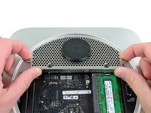
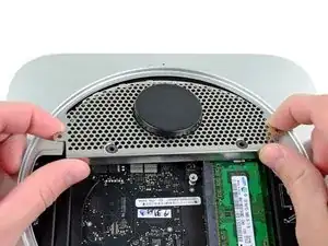
    • Hebe das Antennenblech leicht von der Seite her an, die am nächsten am RAM liegt.

    • Ziehe das Blech vorsichtig von der kreisförmigen Rille des Gehäuses weg.

    • Entferne das Antennenblech noch nicht. Es ist immer noch mit der AirPort/Bluetooth Platine verbunden.

    Here's where it started going south on me because the two T8 screws aren't really attached to anything because my hard drive is on the top of the case where the DVD drive used to be.

    jpmist -

    The top curved part of the antenna plate has a thin lip on the bottom edge, but is very flexible. During reassembly when sliding the antenna plate back into position, if the 4 holes do not exactly line up, then try bending that lip downward a bit and the antenna plate should then line up perfectly.

    Eric Demopoulos -

    Actually, curved edge of antenna has a groove into which an edge of aluminium body should slide in. In my case a vary slight lift by putting tip of tweezers into one of the antenna top holes made a good help - antenna popped into correct position.

    Jurgis R -

    Thank you! Helped me in my 2012 mini.

    Edmar Herrero -

    On reassembly, I could engage either one of the two ears, but not both at the same time. _Lifting_ the antenna plate slightly with a paperclip bent into an “L” and inserted through one of the holes close the the center of the curved edge did the trick for me.

    Andrew Black -

    Adding 2nd drive to Late 2012 2.6GHz i7 Mac mini

    This is as far as I had to go with disassembly.

    Disconnected & eased out original 1TB HD. Removed the two grommets on its side and switched the 1TB HDD with the new 2nd drive cable (not quite the same as the one illustrated here – mine consisted of just the cable and no cradle ). Eased that HD back in and attached it to the previously spare drive socket on the logic board (with drive at the top, right-hand looking down). Screwed 2 grommets into my new 500GB (7mm) SSD, attached old drive cable and eased the SSD in on top of the old drive. Connected that drive to the first logic board socket.

    Took a while aligning the antenna plate and the 2 inner screws didn’t seem to line up with the new SSD so in the end I left them out. Everything seems secure, though. Cowling slipped back in place with no problem and that was it.

    Currently cloning the old HDD onto my new SSD with Carbon Copy Cloner. So far, so good. Can’t believe how easy it was – just 10 steps rather than 37!

    Roger Houghton -

  10. KkUOIGsW6IuaiREO
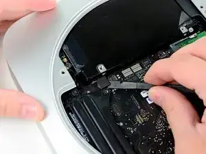
    • Mit der Spitze eines Spudgers löst du vorsichtig den Antennenverbinder aus seinem Sockel auf der AirPort/Bluetooth Platine.

    steps 10 11 13 14 15 16 not necessary …

    1 2 3 4 5 6 7 8 9 12 17 only needed to change hard drive …

    radioman -

    You were right.

    kurtsaban -

    yep worked for me too

    kate henderson -

    Worked for me too.

    ablack3 -

    Absolutely correct. Thanks. The wide-head screws holding in the antenna plate may be used on the upper side of the HD (SSD in my case) to help hold the side of the HD that slips under the case -up- so the two side mounting screws in the drive may be seated properly in the case. This is easier to do than to describe. (Others have noted this, as well and I followed the advice.)

    barryjaylevine -

    This, agreed. Do as Radioman says. Far less complicated and I had everything apart and back together within 10 minutes.

    Chris Belanger -

    Step 10 is different for late mini Mac 2012

    The antennaplug is different (round)

    Josse -

    That s why it is easier to leave it on the logic board at all times

    There is no need to remove it.

    Carefully let it follow the logic board assembly when you take that it out completely in the nex steps.

    Bas Meijer -

    Agreed. I just rotated the antenna plate out of the way.

    barryjaylevine -

    unless, of course, you are here to replace the logic board

    maccentric -

    I skipped steps 10 and 11 but had to do the rest to get the drive out. My system had a second drive so that may be why the logic board had to be removed to have enough room to get the drive out past the DIMM sockets.

    Craig Foster -

    On the Late 2012 model the antenna connector is hidden under the case, so unlike as indicated in step 10 you can not see the connector and definitely not remove it until the Logic Board has been eased out an inch. Note how the cable makes a loop under the case as it is removed. Remember to reconnect the same way with the loop and connected before the logic board is pushed in all the way.

    Indy -

    The antenna connector is underneath a black flap. I just lifted the flap slightly with a spudger and used my fingers to disconnect.

    FinnCrisp888 -

    ...in the latest delivery of the mac mini they had changed something. The antenna plug is hidden under a plastic cover and some tape on it.

    You have to push up the cover and remove the tape...not really difficult, it was formed so you can put up easilly.

    Tom -

    If your machine came with a 7mm drive and you are replacing with a 7mm drive you do not need to move the logic board. I installed an Intel 335 240GB drive which is a 9.5mm drive and to get that drive in I did need to bump the logic board out to clear the memory slot brackets. I did not need to remote any other wires or connections as the logic board only needs to move maybe an 1/8" to get the drive to clear the memory bracket.

    klaubscher326 -

    When removing the wifi antenna make sure you use a plastic spudger and lever up underneath the wire. I used a metal screwdriver and levered up from the side opposite the wire and ripped the pico-ITX connector right off the board! Fortunately I only use my mini via Ethernet, but now I have no choice!

    Kevin Broadey -

    Did you actually break it? It pops out easily and can actually be plugged back in easily too with tweezers or small needle nose pliers. I did the same thing with no permanent damage.

    Steen Rancher

    January 12, 2015

    Steener -

    I skipped this step with no problems.

    manwe -

    I have a late 2012 Mac mini, but it must be an earlier version than this late 2012 Mac mini in this description, because removing the hard drive is much more complicated than described here. Please see this YouTube video if you have trouble removing your hard drive with these directions. https://www.youtube.com/watch?v=cvmuQIZP... There is a longer process you've got to go through. It can be done, it just takes much longer. (3-4 hours for me)

    sandyfacebook -

    I think sandyfacebook is speaking about the mini server with the second drive this guide is about replacing the primary drive.

    BTW, I agree with radioman: it MUCH safer if you do not need to remove the logic board to replace the HD. Just stop after step 12 and pull the drive out. The trouble starts when you try to put it back in because gravity is working against you: the drive has to hang in its slots about 1 cm above the top casing, which is on your table. The trick is to flip the mini up onto its front edge and after a couple of tries the buttons on the HD will engage their sockets.

    rsjrsj -

    Am unable to reattach the cable to its socket on the wireless board of my late 2012 (after installing SSD as second drive). Looks roughly the same as pictures here, but won’t attach. Anyone had problems attaching and figured it out?

    foosayer -

    On my late 2012 Mac mini, I could not slide out the lower drive without removing the logic board; the memory cards were in the way. Radioman’s suggestion may work for some disks, but not for mine.

    Andrew Black -

    Thanks sandyfacebook, I also had a 2012 Mac Mini (not the Server version) where the Primary drive was installed in the top (that is to say, lower when the Mini is upside down to be worked on) drive slot. This meant a complete disassembly was required, removing the logic board completely, along with the PSU and lastly the lower drive caddy. Unlike the drive shown in the pictures, the one underneath is secured into the caddy with screws and cannot be just lifted out.

    stuart.johns -

  11. XIW1QpyHMwWIqRNS
    • Entferne das Antennenblech vom Mini.

    There's no real need to disconnect the antenna. You can just lay the grill gently on its side and leave it connected.

    FinnCrisp888 -

    That is true if you do not need to remove the logic board (i.e. you are only replacing the drive in the original slot position).

    anonymous 3693 -

    You can leave the antenna plate attached and remove the logic board if you're careful while removing the motherboard.

    Dan Wilson -

    You might find the two silver screws (along the edge of the grill) will not attach. That's because the hard drive was installed a millimeter or two in the wrong place (or maybe the new hard drive has screw holes offset, in the wrong place). This happened to me. Rather than take it apart (again), I'll just secure the two screws that go into the tabs. No question this will keep things secure enough (just a question if I'll suffer noise or rattle). Extra screws are fun :-)

    scootz -

    You can gently use the tip of a screwdriver to align the antenna plate screw holes as long as your hard drive pegs are aligned. *DO NOT FORCE* as your hard drive may just not be in the right place.

    Drew -

    On my Late 2012 mini, the antenna plate connector is covered by part of the case. But, as FinnCrisp888 said, there is actually no need to remove the antenna plate at all; just carefully fold it back to expose the bottom drive.

    Andrew Black -

    Has anyone figured out how to reconnect the antenna wire back to the logic board?

    Phillip Mullins -

  12. gFshH6jov5IGgQLl
    gFshH6jov5IGgQLl
    3ypkU5QZ6vDwFdHL
    • Benutze das flache Ende eines Spudgers um den Verbindungsstecker der Festplatte aus seinem Sockel auf dem Logic Board zu lösen.

    It may just be my own experience, but the hard drive connectors appear to be "sensitive" to ANY pressure, even when (re)connected properly. I found that I had to repeatedly re-seat them when re-installing the drive, AirPort antenna, and cowling. I would recommend holding off on putting the screws back for the AirPort antenna and cowling until both are in place, and re-checking the hard drive connectors before installing/tightening those screws.

    UNSC Jon 117 -

    Note the hard drive connector attaches to the outermost connector on the logic board. On my Mini it attached to the inner connector.

    The cable I got in the Dual Drive kit was exactly the same as the one installed in my Mini. I had to fold it to shift it over to snap on the outer connector.

    And, no, my hard drive wasn't where the picture shows it to be.

    jpmist -

    As UNSC Jon 117 says, these connectors are worryingly prone to pop off if there's any movement of the drives. Fortunately they're accessible even after refitting the antenna plate, so I would wait until then for a last-minute check. I've done this job three times now on the same Mac and everything has been fine.

    Charles Butcher -

    The server version of the MacMini 2011 has three extra two wire cables for temperature sensors: two on the drive directly under the antenna plate, one on the other drive.

    The small connectors have to lifted up from the logic board just like the fan connector and the IR sensor connector.

    Take care when transferring the sensors to a new drive because two of those three extremely tiny PC board need to be removed of the old drive and are glued in place.

    ernstcline -

    The "pop off" seems only to happen during reassembly if you press on the harddisk body. The harddisk at this time can be pressed in the direction of the underlying drive (in my case a SSD Drive) . Once the grid with the antenna has been attached (two red screws in step 8) this cannot happen any more.

    John Doe 9th -

  13. AayZoHCA511Q2NVe
    • Löse den Verbindungsstecker des Infrarotsensors mit der Spitze eines Spudgers vom Logic Board.

    • Achte darauf dass du unter den Kabeln hebelst und nicht unter dem Stecker selbst.

    This board component is very delicate, I screwed up my Mac Mini IR receiver and HDD led light by doing this wrong. PLEASE take your time to do this delicately.

    lcba813 -

    I have the same problem. I damaged the connecter for IR Sensor which is on the Logic Board.

    Is there a way to fix it?

    macnaf@orange.fr

    Michel -

    On my 2012 mac mini, the IR sensor was just soldered to the board--no connector that you could snap out. I have never used the remote with it, so I just let it disconnect. But I did have a few moments of panic while I remembered what the IR was for.

    AG -

    Anche a me e' successa la stessa cosa : si sono staccati i pin saldati alla piastra madre e non ho potuto riattaccare lo spinotto dell' IR sensor....esiste un modo per ripararlo?

    Ignazio Lussu -

    This connector can be repaired with the right tools and know how. Using an SMD hot air station or possibly even a professional quality soldering iron with a needle point tip is how you would approach it. I repaired mine—which I busted loose, of course by rushing things and pulling too hard—using a hot air station, but it was very tedious work requiring magnifying head gear and special low temp SMD soldering paste. Not an easy fix even with the right tools.

    S. M. -

    Yes, this is extremely fragile. A couple of the pins on the logic board broke off. They are very tiny pins that are secured to the board surface with solder. I was very careful with it too, but they broke nevertheless. There is no repairing that when it happens. Thus, I have no IR sensor (which I never used) and no front LED (minor loss - not worth the cost of a new logic board). Works fine otherwise.

    davidw -

    Mannn this part is difficult. Tks for my girlfriend that disconected it for me. Hands of fary!

    luiscortex -

    I also just snapped this off by levering at the wrong point. So this is just for the IR sensor and the flashing light? If so, I'll just ignore it and happily carry on with life without these two features that I never used or noticed! I've been searching for someone who can do the delicate welding to reconnect the 5 pins but if what you say is true I'll stop searching.

    Recommend emphasizing even more in the instructions, the potential for disaster!

    warren -

    The pins connect into the edge of the connector, not the top or the bottom. So, you should pull it out parallel to the logic board in the direction of the wires, towards the front of the case.

    When reassembling, it's easier to connect this before pushing the logic board in all the way.

    TerribleHacker -

    Also: do not attempt to bend the pins upwards to install, and then bend it back. I broke 3 pins that way.

    It easier if you unhook the wires from a couple of tabs on the side attached to the case. That allows more leeway to manipulate the connector. There are two plastic tabs, and the wires are routed between them so that they do not move out of place.

    I suggest taking a good close-up photo so you can see how the parts fit together. That's how I was able to figure out what I was doing wrong.

    TerribleHacker -

    TerribleHacker: "pull it out parallel to the logic board" – no, or at least not on mine. The pins are vertical and the socket has two vertical tongues that fit into grooves on the plug. Vertical is the way to go. In cases like this I use tweezers to pull gently on the wires, and if possible the plug – but the latter is very difficult in this case.

    Charles Butcher -

    Yep. Like others here I no longer have IR. Be VERY careful removing this!

    Bryan Schneider -

    TAKE YOUR TIME!!! I used the spudger and pushed up from the back on the plastic, NOT the wires. And I had no issues. Pulling on the wires scared me way to much. Pull up vertically.

    Will Vernon -

    Before attempting to remove the connector, use 5 minute epoxy to glue the wires together. Do this in several small batches and apply with a toothpick, right up to the plastic connector, but not glued to the connector (to risky and not necessary). Be especially careful not to glue to the motherboard. You basically want all 5 wires glued together as if they were a ribbon cable. After the epoxy is cured, pry up from underneath the wires to remove from the motherboard.

    Moldyjohn -

    I could remove the HDD and then was able to use the folded spudger from the hdd side of the motherboard to _easily_ pull the connector up from its corners (not via the wires).

    Grigory Entin -

    I lost my IR sensor and HDD led light as well. Everything was moving along smoothly and I got cocky with the spudger and lifted the connection out of the board. I reassembled with the upgrades and it ran just fine. Like others, I had never used the remote and couldn’t see the HDD light where the mini sat on my desk anyway.

    Peter Bovey -

    yes, there is a way to FIX it, solder it back ! :) that’s what I did on mine

    Hubert H. -

    The best way is to first remove the logic board already 0.5 cm out, like discribed in the next steps. Look closely at the wires, they tell you how far you can go! Then take a cotton swab, cut off the cotton ends ending witha plastic stick, bend the end to get it easily under the wires and pull it carefully upwards. The connector then comes off in one piece.

    Bas Meijer -

    The best way is to first remove the logic board already 0.5 cm out, like discribed in the next steps. Look closely at the wires, they tell you how far you can go! Then take a cotton swab, cut off the cotton ends ending witha plastic stick, bend the end to get it easily under the wires. Take both ends and pull it carefully when it is as close as possible to the connector. The connector then comes off in one piece.

    Bas Meijer -

    Must really concur with Bas Meijer’s suggestion. Move the logic board slightly first then it is a breeze to get under the wires and lift up.

    Mal Watson -

    As the warning says “pry up beneath the wires, not beneath the socket”. The connector lifts out, but is surrounded on 3 sides by walls of the socket. Don’t lift the socket off, lift the connector out. Easier after step 14-15 and you move the main board out just slightly.

    Greg Nash -

    Does anyone know what is the name of the connector cable side ) I want to buy a new one as mine is damaged and repair it.

    Andrei Constantinescu -

    I am also wondering if I can purchase the side that was on the mother board?

    dogus aslan -

    Unfortunately I bent two of the pins in the process. Moving them back into position broke them, although I was very careful. I felt so stupid. Who the heck at apple thought this is a good design to connect things?? I thought the mini is already lost. Happy to read this cable is not super important, so I will carry on.

    dennis -

  14. OixNJGHMGToYONLE
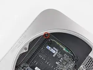
    • Löse die folgenden drei Schrauben:

    • Eine 5,0 mm T8 oder 2,0 mm Sechskantschraube (beide Schraubendreher funktionieren)

    • Eine 16,2 mm T6 Tox Schraube

    • Eine 26 mm T6 Torx Abstandsschraube

    Hi, I can't remove the yellow screw, I don't even see it (it look like more like on this picture: http://static.macgeneration.com/img/2012...)

    So I don't know what to do, I don't want to damage the tread (if there is actually one..) and I can't move the logic-board..

    Do you hav any idea?

    broussesimon -

    The "yellow screw" depicted in this picture doesn't exist in the Mac Mini late 2012, at least in mine. Well, to be more precise, it exists but was already removed when the fan was unscrewed (it was actually in the fan).

    Jeff Evans -

    I found the same as Jeff.

    Martin Cleaver -

    For reassembly, note that the red T8/2mm hex screw doesn't screw all the way down. It is for the bottom lid to slide-lock onto. Don't look for a hole beneath it on the logic board.

    malcolmgin -

    this yellow screw come from fan , on the image in front missing exactly this one screw (yellow circle)

    Christopher -

    any idea in how to remove a stuck the "green” screw ?

    MF_Bra -

    The yellow screw (fan stand off) on my late 2012, was removed with the fan.

    Peter Stockwell -

  15. vCdil4TP3cRWNykL
    vCdil4TP3cRWNykL
    PaneRS5uGgwCvebk
    soFKe4ZlaSRWkHM1
    • Um die Hauptplatine zu entfernen müssen die beiden zylindrischen Stäbe des Mac Mini Logic Board Removal Tools in die beiden rot markierten Öffnungen eingeführt werden. Führt man Instrumente in irgendwelche anderen Öffnungen als die rot markierten auf dem Logic Board ein, kann es zerstört werden.

    • Führe also das Mac Mini Logic Board Removal Tool in die beiden rot markierten Öffnungen ein. Achte darauf, dass es Kontakt zur oberen Seite des Außengehäuses unter dem Logic Board hat, bevor du weitermachst.

    • Ziehe das Tool vorsichtig in Richtung des I/O Boards. Das Logic Board und die ganze I/O Board Einheit sollte etwas aus dem Gehäuse rutschen.

    • Beende das Ziehen, wenn du siehst, dass das I/O Board sich sichtlich vom Gehäuse gelöst hat.

    • Entferne das Mac Mini Logic Board Removing Tool.

    If you're in a pinch and don't have time to order the removal tool, you can use two 2mm hex wrenches.

    philomathius -

    You can also use the probes from a Digital Multi-Meter. Just be very careful not to stab the pointed end into the casing. With a little care, you can get the logic board out.

    mattgarfield -

    On re-assembly, when you're putting the HD back in place, before you've pushed the logic board fully back into place, make sure the disk is in the right place for the antenna plate screw holes (step 8/9) or you'll have problems getting the screws back in. I did, and had to back up a few steps to realign the disk drive!

    Kevin Broadey -

    Look at all of the images. Initially, I took the text literally. I pulled the tool straight back without letting it pivot, and without success. I suggest the following additions: "The tool acts as a lever. Carefully pull the top of the tool down and toward the I/O board. The logic board and I/O board assembly should slightly slide out of the outer case."

    anonymous 1829 -

    A length of coat hanger wire bent to the width of the two holes worked fine for me.

    jpmist -

    Thanks for that tip! A couple wire-hanger lengths worked for me too..!

    steve375 -

    If you don't have the removal tool you can just plug an ethernet cable into the I/O port and pull on it to help ease it out...if it's a bit stiff push on the fan duct at the same time...be gentle and it'll release...

    Jim Fixesthem -

    I found that there is one step missing for removing the logic board. Once you have the removal tool in and pulling back check to see if you can push in on the taps that are on the outside of the logic board. On the right side if I had known this I would have tried pushing in on the tap and it might have released a little easier. There is not a good photo of the taps but in photo 17 between the pointer and index finger the tap is located on both right and left hands.

    mary7654 -

    Even better, you can just use one of your screwdrivers if you do it carefully, just push out each side a little bit and rock out the logic board. No special tool needed. Just be careful not to damage your logic board and/or apply too much force.

    Drew -

    If was able to fashion a removal tool out of part of a metal binding clip. I just removed one of the handles and bend it into the proper shape using a vise. FYI, the holes are about 4.5mm apart.

    drewmc -

    I’ve used an Allen key of the right diameter.

    it worked very fine!

    skullerm -

    I just pushed on one of the RAM slots and it slid out easily. No metal rods required!

    Ragnarok -

  16. 5AVpNqwjXEaVetVI
    • Ziehe die ganze I/O Board/ Logic Board Einheit weit genug aus dem Gehäuse, um an die Stromversorgung zu kommen.

    • Löse mit den Fingern das DC-In Kabel vom Logic Board.

    • Ziehe den Stromkabelanschluss in Richtung der Vorderseite des Mini.

    You can pull the board out about 1cm with the wires intact.

    Martin Cleaver -

    While you can remove this pin with your fingers as shown in the photo, putting back in proved frustrating by hand. I finally got out a forcep which allowed me to grab each side of the plug and push it in at a flat angle.

    Dan Ochiva -

    I found way easier to remove the power wire line by removing the hard drive (loose already) first!

    alextc -

    This made all the difference.

    Lee Fuhr -

    You're a hero.

    kazoodac -

    excellent tip!

    Rog -

    When reconnect it on the board, make it when the board is in the middle of the mac, or you will be not abble to do it!

    luiscortex -

    I'm not a fan of pulling on cables so I used the flat end of the spudger and pried between logic board and light thicker end of the DC plug. This took some time but worked really well.

    mhomscheidt -

    I found that slightly lifting the board allowed me to get the connector in a better position to rest on its female counterpart. Then with a smudger just push it into place.

    Tony Visconti -

    When getting it back on during reassembly, your spudger is your best friend.

    Do this when the logic board assembly is not completely inserted back in again.

    Bas Meijer -

    If you removed the hard drive during disassembly, when reassembling you'll want to put it back before sliding the board back into place.

    maccentric -

  17. fTgiLowRdkdLPeeB
    • Ziehe vorsichtig die ganze Logic Board Einheit aus dem Mini, und passe dabei auf, dass kein Kabel hängen bleibt.

    In April, I purchased a late 2012 mini (MD387LL/A) - 2.5Ghz i5 with 500MB hard drive.

    It looks like Apple now secures the drive to the tray with 3 screws. 2 on back side and one on front. This means the entire drive tray has to come out to remove the drive - it no longer just "lifts out" as in step 18. In order to remove the drive tray, you have to remove the power supply (step 22).

    Gary Leatherman -

    During reassembly, watch the power harness and connector from the power supply when reinserting the logic board assembly into the case. When the board is close enough for the connector to reach, re-attach it before inserting the board the rest of the way. I found that if the connector is lined up properly, it almost attaches itself.

    Also be careful of the hard drive and IR sensor connectors.

    UNSC Jon 117 -

    Also, when you're re-assembling (especially with a tight squeeze if you've got dual drives), be sure that the internal AC power connector matches up in profile with the port outline on the rear plate of the main logic board assembly. If the two aren't mated identically, the black port plate won't mate flush with the aluminum case.

    johnkimmel -

    Speaker trademark? Is it a sony, or a Bose...

    I think it is a bad quality speaker.What do you thick?

    Hugo BURGUILLOS -

    Does anyone know if the airport/bt board from a mac mini late 2012 can be retrofitted to the 2011 mini? this would add the airdrop functionality to the older device in theory and I have seen a similar procedure performed on MacBook pro's

    Steven Fox -

    When I pull out motherboard, I broke 39 16v capacitor underneath.. I don't understand what's I'm doing wrong. And why this happens? Or maybe I'm to fast. Now I need repair..

    Flanua -

    I did the same thing, except two caps popped off the board. Perhaps drinking half a fifth of whiskey before starting this project was unwise. Although, if the sucky SATA cable that came with the ifixit kit had worked in the first place, I wouldn't have had to pull the thing apart again to replace it with the OWC cable (which supposedly doesn't suck).

    scoventon -

    During reassembly, the SD Card reader end of the I/O Bezel will not go back in flat like the AC power connector end, thus the SD Card reader end protrudes about 0.5mm from the edge of the back of the MacMini, I tried took it out and put it back in many times but could not manage to push it all the way in. The truth is it is hard to notice and everything else works fine but it is annoying to see that tiny bit protrusion. Anyone else had this problem? or it was like this already before I took it out? i can't remember what was it like now.....

    neo.hsu -

    During this process, I took advantage of having the logic board out, checked the BR2032 battery, which tested nearly dead, and I replaced it with an ECR2032 battery. If you choose to do this, be careful with the moving and replacing of this button battery. There is a wee-little directional arrow on the ( - ) side of the battery holder, which means move the battery without prying towards the positive ( + ) side. One end of the battery then pops up to grab. I also tested the new replacement battery before putting it in. I used an AMPROBE BAT-200 Battery Tester.

    Carrick -

    So near and yet so far. Got as far as this stage only to fail.

    If you look closely at the photo for this stage, just up and to the left of where you unplug the power cable, you will see a white wire going into a grey sleeve attached to a grey plastic plug of some description. That’s not what I have. What I have is five wires, two of which (one black, one brown) have tiny copper clips which suggests that they were attached to the logic board. The other three wires (two black, one grey) look like they were torn off and damaged during the removal. I’d post a photo but there doesn’t appear to be the facility for it.

    C’est la vie.

    stevie.g -

    Would it be possible to insert the lower disk at this step without removing all the remaining parts ?

    fra -

    I achieved to insert the lower disk at this step without removing all the remaining parts !!! You just have to screw the HD on the other side (motherboard side).

    fra -

    I too, took advantage of replacing the 3V #2032 PRAM lithium battery. Doesn’t make sense not to, since it’s completely torn down.

    Val -

    I found that cloning the new SSD drive before installation sidesteps 'hybrid' drive issues.

    I didn't disconnect the antenna cable since it's very tricky to reconnect that tiny connector.

    The original drive in my unit is positioned at the bottom and I couldn't get that out without dissembling everything so I just left it in place and disconnected the cable.

    I moved the logic board back about 2" to give me some wiggle room inserting the new drive.

    I couldn't get the new drive to fit into place with the rubber washers inserted on the posts so I just used the posts instead which gave me some more room to push the new drive back far enough to fit into the positioning holes.

    Even then the cable for the new drive took a lot of effort to connect to the board since I think the new drive still didn't fit perfectly above the older drive.

    I used scotch tape to help position the new SSD.

    Overall a huge speed improvement from the old spinner.

    For me this was a more than moderately difficult project.

    k.lang -

  18. UbakqAJxFiyFoEao
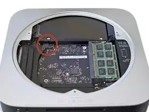
    • Du findest die PRAM Batterie oben am Logic Board.

    • Hebe die PRAM Batterie mit der Spudgerspitze aus der Halterung auf dem Logic Board.

    Symptoms of a failing battery: USB locks up, no input from mouse or keyboard after computer has been idle for a while, but previous screen image either persists or blacks out (except for mouse pointer, at times). Batteries are cheap at most pharmacies, look in the hearing aid battery section, number 2032.

    owen -

    If your unlucky like me and your battery has exploded corrosion all over your logic board, a little bit of 70% to 90% rubbing alchohol on a que tip cleans it right off!

    Drew -

  19. QaQA2jUGvtCBFZFw
    • Entferne die PRAM Batterie vom Logic Board.

    • Die PRAM Batterie ist eine handelsübliche Knopfzelle vom Typ BR 2032.

    Be careful to lift the battery out at the angle shown here. You may need to use a spudger to get it started. The little plastic overhang on the left side of the battery clip in this picture is extremely easy to break! And it’s the only thing that holds the battery in place.

    Rog -

    My battery isn’t in that position, it’s diagonally opposite, under the RAM.

    Broad Gavin -

    I have the Server Version and the battery is under the RAM too.

    ccfman2004 -

Abschluss

Um dein Gerät wieder zusammen zu setzen folge den Schritten in umgekehrter Reihenfolge.

Walter Galan

685541 Reputation

5 Kommentare

Great directions. Unfortunately it’s the logic board. But thanks.

Craig Wallace -

Second time I have used this guide. Thorough and NO fluff…i.e. When the guide says “gently" or “can be difficult" those words are there for a reason. This one is direct and to the point without a head in the clouds. Leave that to me!

John Heins -

The PRAM battery is a commonly available BR2032 coin-cell.

By mail order only and from China for me, Ordered two BR2032 coin cells 12 days ago and still waiting. I doubt if you would find this exact type anywhere locally in a store. You could go with a CR2032 which is found more easily but after what I found online it does make a difference.

The main difference between these two types resides in their electrode.

While similar, the BR2032 uses carbon monofluoride as the positive electrode.

The CR2032 uses manganese dioxide for the positive electrode
David Bell -

There is a difference between CR2032 and BR2032. While the dimensions are the same, the chemistries are different. The BR2032 are preferred for maintaining computer PRAM or BIOS because at temperatures above 60c (140f) the CR type battery decays faster and has more voltage sag. It is not unusual for the inside of your computer to reach these temperatures. In relatively speaking higher drain applications -like many consumer use applications, the chemistry of the CR type battery is advantageous as it provides more steady voltage under higher drains at temperatures under 60c. In short, after 3 or 4 years in a system the CR chemistry battery might not be providing close enough to the 3v for the system clock to maintain the purest accuracy. But can you use either?- yes. But what does Apple put as factory original? - the BR chemistry.

David Bell -

Why is a fan listed as a part? Is it expected to be destroyed in removal? That seems unlikely.

William R. Dickson -