Einleitung

  1. fDIVxaq2KuA4ecer
    fDIVxaq2KuA4ecer
    FlXcWPU4JQhRHpc1
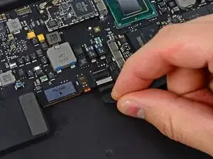
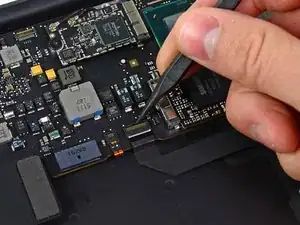
    • Klappe den Halteclip auf dem ZIF Sockel des Tastfeld-Flachbandkabels mit der Spudgerspitze oder einem Fingernagel nach oben.

    • Achte darauf, an dem klappbaren Halteclip zu hebeln und nicht direkt am Sockel.

    • Ziehe das Tastfeld-Flachbandkabel gerade aus seinem Sockel heraus in Richtung der vorderen Kante des Geräts.

    Disaster strikes. I pulled away the socket itself (just like it says not to). Is there any possibility to re-connect it, or did I just ruin the whole logic board?

    Nigel Anderson -

    I lost the retaining flap so I don’t know if it can stay in place without the retaining flap

    SK Alias -

  2. 26x2mxNFQNjqcFy5
    26x2mxNFQNjqcFy5
    FgfhRF5assrEBADX
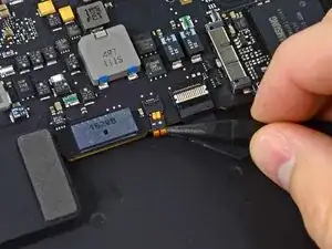
    • Klappe den Halteclip des Flachbandkabel des ZIF-Sockels der Tatsturhintergrundbeleuchtung mit der Spudgerspitze nach oben.

    • Achte darauf, an dem klappbaren Halteclip zu hebeln und nicht direkt am Sockel.

    • Verwende den Spudger, um das Kabel aus der Fassung herauszuholen.

  3. NMFq34d1KowEZwie
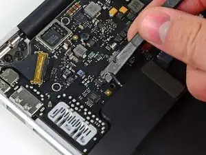
    • Heble den Kabelstecker der rechten Lautsprechers mit einem Spudger nach oben und entferne ihn von seiner Fassung auf dem Logic Board.

    • Setze mit dem Hebeln unterhalb der Kabel an.

    To snap back in, place speaker cable connector directly on top of socket and press down with your finger or tool.

    anonymous 6745 -

    This has to be done very gently. I only applied a mild lift and the socket broke off from the board. I had to say good-bye to the right speaker. :-(

    Kuro Kurosaka -

    Read my comment about using tweezers for the left speaker cable connector. But for some reason, the right connector was a little more tight and took more effort than the left speaker cable connector.

    Mark Kilpatrick -

  4. Xb6iQ6MGaJTTkGOy
    Xb6iQ6MGaJTTkGOy
    O4v4obM3TderKAwS
    KJCRgFpNAPD1BvsS
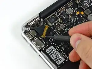
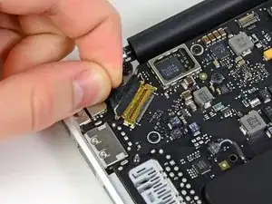
    • Drücke vorsichtig die Spudgerspitze gegen den schwarzen Kunststoffclip, der am Displaydatenkabelschloss angebracht ist, so dass das Schloss nach oben und weg von dem Sockel poppt.

    • Während du das Schloss von der Fassung auf Abstand hälst, entferne mit einem Spudger und deinen Fingern das Displaydatenkabel aus seiner Fassung.

    • Ziehe das Displaydatenkabel nicht nach oben, wenn du es trennst, da ansonsten die Fassung vom Logic Board brechen kann.

    Regarding the second photo on step 22, I believe the placement of the spudger is incorrect. If the second photo's purpose is to demonstrate the placement of the spudger described in the second bullet--"...use the tip of a spudger and your fingers to gently remove the display data cable..."-- then such placement could lead to damaging the connector. View this annotated screenshot to see what I'm trying to convey: https://www.evernote.com/shard/s4/sh/1f5....

    Christopher Fernandes -

    I agree, I used tweezers to pull it gently and it worked beautifully

    Gian Carlo -

    Agree. Use tweezers.

    sdcsoup -

    You should place the tip of the spudger on top of the connector and push out. At first I had the tip of the spudger on the bottom and tried to push up and that was incorrect.

    Mark Kilpatrick -

  5. 3LFmTyGYQY2FCAXH
    3LFmTyGYQY2FCAXH
    kDScRNQOoHVGVCTo
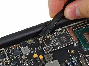
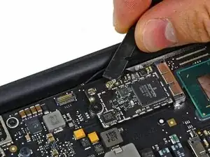
    • Heble beide Antennenkabelstecker mit einem Spudger nach oben und entferne sie aus ihren Sockeln auf der AirPort/Bluetooth Karte.

    When reconnecting, how will I know which cable connects to the connectors?

    Ringo CoC -

    Fits oneway only. See length of the cable connectors

    yuroen -

    I put a small piece of red tape on the right wire to identify.

    kcunningham -

  6. C5ccyvfJpYDwhYtW
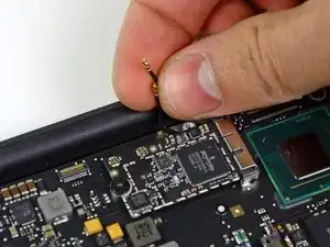
    • Hole die Antennenkabel vorsichtig aus ihren Slots auf dem Logic Board.

  7. i6a4NeJdAQ6AaIFk
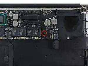
    • Entferne die einzelne 2,85 mm T5 Torx Schraube, mit der die SSD am Logic Board befestigt ist.

  8. xSOPJU2j26YFYOLD
    xSOPJU2j26YFYOLD
    Rd4YjLZ4Z2M1gfJp
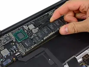
    • Um Schäden am Anschluss zu vermeiden, hebe das Ende der SSD nicht zu stark an.

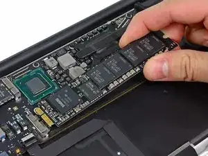
    • Ziehe das Laufwerk gerade aus seinem Anschluss heraus und entferne es vom Logic Board.

    • Wenn du die SSD wieder einsetzt, gehe sicher, dass sie richtig positioniert ist, bevor du die Schraube wieder eindrehst.

    Warning: there may be adhesive keeping the SSD in place. i got 1 with, and 1 without, both slightly different models (but still the same model name, A1466 )

    divinity76 -

  9. NtEXvesjKHkLKitt
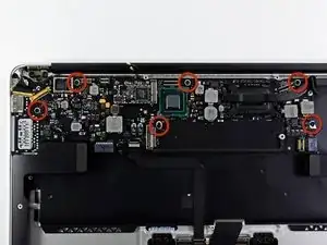
    • Entferne die sechs 6,3 mm T5 Torx Schrauben, mit denen das Logic Board am oberen Gehäuse befestigt ist.

    Please Please Please remember to re-attach your antenna cables if you are replacing the upper case with a new or refurbished one. They have a way of slipping under the logic board.

    Timothy Button -

    These screws are easily stripped. If you accidentally push too hard, you will strip the screw when re-attaching. If that happens, get a pair of needle nose pliers and gently work the screw out taking care not to damage the board.

    Timothy Button -

    My screws were 4.xx mm

    Gabe -

    These screws are actually 3.6 mm T5 Torx. Please fix :)

    Doc Halstater -

    I’ll second this observation.

    sjosefw -

    When putting the logic board back, make sure the speaker wire isn't trapped under it

    Shiv Sikand -

    I have not replaced a display on the A1369 but have done many A1466 which is a newer 13” model. They seem really similar and its not clear why one needs to remove the logic board to remove the display. The antenna cables on the A1466 dont have to rest under the logic board but can be tucked in the hinge crevice. Cant this same thing be done with the A1369?

    Sean Love -

  10. o4CW5xU4RPKgXWeF
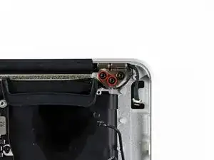
    • Entferne die inneren zwei 4,9 mm T8 Torx Schrauben, mit denen der Antennenkabelhalter und das linke Kupplungsscharnier am oberen Gehäuse festgemacht ist.

    These are T9-sized torx screws, not T8.

    Hanii Puppy -

    This is good to know. I think I need to order a screwdriver set - all I have is the pentalobe and one other that came with my SSD replacement kit.

    forestsprite -

    I also had T9 screws on my device.

    I found it helpful to loosen the 3rd screw of the hinge already a TINY bit. The screws are quite tight so it´s easier to loosen them while the case is lying flat on the surface. This procedure comes in handy in Step 34 where you have to hold the case perpendicular with one hand, while unscrewing this screw with the other hand.

    wolfgang07 -

    Mine were T8 screws, but I was able to use a T9 torx with pressure and that worked.

    kcunningham -

    fyi, mine were T8

    jmull -

    My hinge screws were T9, and fit very snugly. If your screwdrivers are not a precision set, such that the T9 is too tight, you can use T8, but it won’t be good for the screw heads.

    Josh -

    Mine were T8 and my T8 bit worked fine.

    Mark Kilpatrick -

  11. Fr26HfIScpCDwxhX
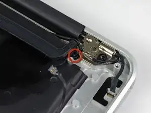
    • Bewege den Antennenkabelhalter etwas beiseite und entferne die 3 mm T5 Torx Schraube, mit der das Ende des Wärmeableiters am oberen Gehäuse festgemacht ist.

    "remove the 3 mm T5 Torx screw securing the end of the heat sink to the upper case" -- an optional step when detaching components from upper case for cleaning, eg after a liquid spilled to keyboard.

    yurkennis -

    When I was re-assembling, the screw hole of the heat sink didn’t align. I applied a mild force then the edge of the heat sink broke off from the rest, losing the contact to the case. I am hoping the Air would work for a while during the test run (if it ever works) but I would buy a replacement heat sink for regular use.

    Kuro Kurosaka -

  12. 2YFhbnVXyfVZdKFI
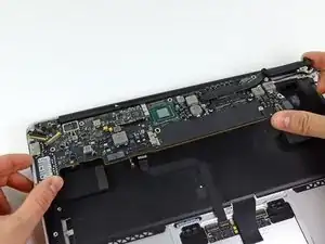
    • Entferne die Logic Board Einheit vorsichtig vom obere Gehäuse und achte dabei auf Kabel, die im Weg sein könnten.

    • Achte darauf, dass die Antennenkabel nicht im Weg sind, wenn du die Wärmeableiter-Seite des Logic Boards aus dem oberen Gehäuse hebst.

    On reassembly, as you seat the board in place, make sure the keyboard backlight cable is not trapped under it.

    davecortesi -

    Removal of logic board and all the steps leading up to it I found unnecessary. They may be good for some but I really didn't need to dismantle the laptop as much as this guide shows to get the display off. Just my opinion, of course.

    Kevin Ginther -

Andrew Bookholt

578335 Reputation

Ein Kommentar

Excellent guide, thank you very much.

Logic board removed from my daughter’s Air, cooked for 8m at 200C, cooled, reinstalled, and now works again.

I was able to remove and replace the 5th heatsink retaining screw without moving the antenna retainer.

Cheers, Aidan
Aidan Killian -