Einleitung

Internal Prerequisite.

  1. wLdGXojtlTEXXu6S
    wLdGXojtlTEXXu6S
    FVZ1fJ3tFfvCPAUb
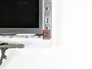
    • Remove the small piece of foam tape stuck down above each of the bezel covers, at the lower left and right corners.

  2. XyRlveFnFLBra2GK
    XyRlveFnFLBra2GK
    APwlGlX1yFqSLBEY
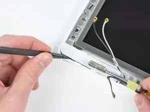
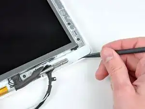
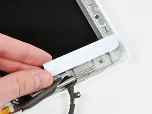
    • Use a spudger to slide the left bezel cover towards the LCD panel.

    • Do not lift up vertically on the cover! Unlike the large display bezel, this one has horizontal hooks to keep it in place. These will break easily.

    • Lift the left bezel cover off the display assembly.

  3. lSmFRCNaRpvWbGpr
    lSmFRCNaRpvWbGpr
    TdndxBoksIEfK2bB
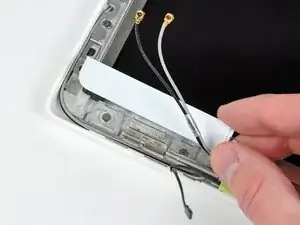
    • Use a spudger to slide the right bezel cover toward the LCD panel.

    • Lift the right bezel cover off the display assembly.

  4. gIwF3Qer6yODuD3g
    gIwF3Qer6yODuD3g
    KL5Oh5naPXhTHTIT
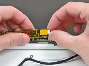
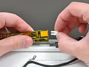
    • Lift the inverter out of the display slightly and disconnect the backlight cable from its right side.

    • Place the inverter back down in its recess.

  5. MhITvtFHVMZiw6xn
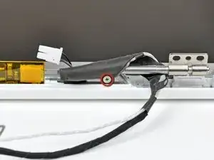
    • Remove the single 3.2 mm Phillips screw securing the display data cable to the right clutch hinge.

  6. upNcpVgeZUPiJ1sV
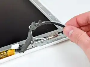
    • Move the display data cable out from under the mounting arm of the right clutch hinge.

  7. xSXX4j1WDLOYoJDS
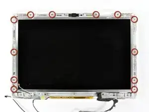
    • Remove the twelve 4.2 mm Phillips screws securing the LCD assembly to the rear display bezel.

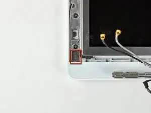
    • Make sure you pay attention to how the microphone cable (and antenna cable on some models) are routed around the outside of the two screws at the bottom left and right corners of the screen. It's easy to damage the cables if not routed properly when reinstalling these screws. To see the cable routing more clearly, click on the photo and zoom in.

    For the re-install, the cables that run along the sides of the LCD display do not follow the entire length of the display on either side. Both the iSight cable and the Airport antenna cables come away from the sides of the display about 3" from the corner where the hinges are. They move to the outside around the aluminum hinge supports. This is important so the cables do not get pinched and the bezel can snap into place.

    kyoungdale -

    Finding the correct route for these cables took some head scratching but the end result worked fine. In hindsight some more detailed pictures of the cable positioning when re-installing would be helpful. I also found that previous Apple authorised repairers had lost screws and removed tape, and charged me £400 for the priviledge.

    Keir -

    What size are these screws? 4.2x? Is there a link to these that would help please?

    Thanks

    Kasim Mohammed -

    To answer Keir's request for more detailed photos of the routing for the cables near the lower left and right corners of the display: click on the photo of the display in this step, which will open a higher-resolution version of the photo in a new tab, where you can click on this photo to magnify it so you can see the cable routing in the corners in larger detail.

    johnsawyercjs -

  8. 4N2ZbUNbplHXLUIK
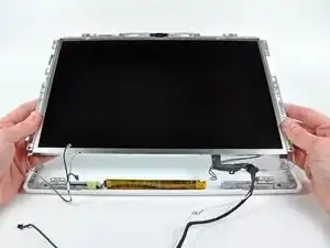
    • Raise the bottom edge of the LCD assembly slightly, then slide it down slightly to free its upper edge from a slight overhang in the rear display bezel.

    • Lift it out of the rear display bezel, minding any cables that may get caught.

    • When reinstalling the LCD assembly back into the rear display bezel, before you tighten down any of its frame mounting screws, make sure the short brass posts, one each on the left and right sides of the bezel, fit into their corresponding holes in the LCD assembly frame.

  9. Aen4jfqbG1d3vopA
    Aen4jfqbG1d3vopA
    nO5s6Go53qyS33gn
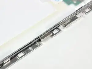
    • Be sure to keep track of the small magnet along the left side of the display. It may be stuck to the LCD frames or to the rear display bezel.

    • When the display lid is closed, this magnet comes in proximity to a sensor on a small circuit board at the bottom end of the I/O board, to tell the Macbook that the display has been closed, so that the Macbook can go into clamshell sleep mode.

    • To reinstall this magnet, press it back into its cavity in the rear display bezel, with its short side facing up (see photo 2), then place the LCD panel back into the rear display bezel and screw it down so that the magnet doesn't drop out and disappear.

    “Make sure to replace the sleep magnet with the shorter edge facing up.”

    Hi, could you please explain to me how and where exactly should be placed this small magnet? I didn’t noticed it when I dismounted and now, from the image, I do not understand where it should be. If you can also explain to me what is it for I’ll double thank you …

    mdirenzo -

    This is quite an important step, as misplacing the magnet will mean that the display will not sleep at all when the cover is closed (which is what happened when I had my broken screen replaced).

    udorotheo -

Abschluss

To reassemble your device, follow these instructions in reverse order.
Andrew Bookholt

578335 Reputation

0 Kommentare