Einleitung

Alles Wichtige zum Austausch des oberen Gehäuses.

  1. dOyroxuUBfNu1T4K
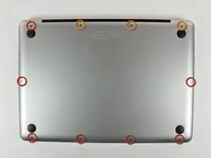
    • Entferne die folgenden 10 Kreuzschlitz-Schrauben, die die Gehäuse-Unterseite des MacBook Pro 13" Unibody befestigen:

    • Sieben 3 mm Schrauben.

    • Drei 13,5 mm Schrauben.

    Compare the short screws carefully before reinstalling them. The shouldered screws go in the holes on the front edge.

    David Kilbridge -

    Before I started removing any screws I took a piece of paper and drew the bottom of the laptop and put a piece of double-sided tape in the spot where each screw goes. That way when I took out the screws, I could put them on the tape so I knew exactly which screw went in which spot. I did the same thing for dismantling the inside on another sheet of paper, then a third sheet for the screen after getting the front glass off.

    mastover -

    I use a similar technique: I print out the iFixit manual for the job, and Scotch-tape down the screws/brackets/cables I remove at each step next to the component descriptions. That way, when I'm reassembling, the bits are taped right next to the photo of where they came from.

    adlerpe -

    That's exactly what I do for all my repairs! It's the best way to keep track of all of the parts ' original location and to make sure that you don't miss any parts during reassembly.

    joyitsjennie -

    Great idea and one I use often

    Thomas Overstreet -

    Excellent idea! Thanks for sharing it here.

    Laura Sharkey -

    I used a 00 that fit but the screws were very tight so I used a tiny paintbrush with some wd40 on it and put it around the edges of the screws. Worked like a charm

    valentinedhdh -

    I use a magnetic mat and place the screws in order on that :)

    Cary B -

  2. bLtKOLyJdyAxkZaG
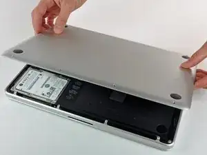
    • Hebe die Unterseite vorsichtig an und drücke sie Richtung Rückseite des Laptops, um die Halterungsclips zu lösen.

    In the introduction you should link fixers to this excellent doc: https://www.ifixit.com/Misc/HD_Software_...

    It is really critical, super easy, and free(!) to clone your existing drive onto the new one you will install. I ran into one error, but SuperDuper! support replied immediately on how to fix it...Thanks ifixit and SuperDuper! (I ponied up the $28 for the software anyway, I was so impressed!)

    Mike -

    Long story short: I drank the AppleKoolAid back in 1984 and have always left the guts of my machines up to Apple - until recently when I needed to swap the SATAs from my original MacDaddy (2009 13" MBPro that I killed in 2018 - coffee + blackout = OOOOPS) into a pristine 2009 MBPro from a Goodwill in North Carolina through eBay. I need the files from iCal and MacMail that can't be opened in my newer machines.

    Well . . . I ain't never done nuttin' like that, before!

    Enter Luke Miani on YouTube. He raves about you guys! So, I watched everything I could, read your site, bought the right tools and at the ripe old age of 72, I sat down, this morning and did the work. Now my original MacDaddy lives in MacDaddy2.0.

    Am I allowed to cry?

    Seriously, I can't thank you enough for your bitchen site and killer tools. I wish I'd'a been turned on to this shizzle 30+ years ago.

    IFIXIT - IDIGIT!

    kath myers -

    HAHAHAHAHAHAHAHAHAHA.

    That was a brilliant read.

    Yes, I came across ifixit a few years ago. Totally helped me out on several occasions.

    Glad your Mac repair journey worked out.

    :)

    Cary B -

  3. B1SUXfcr5fruMavs
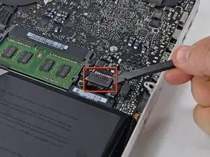
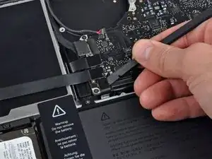
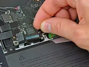
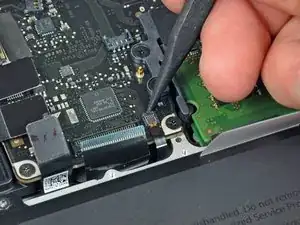
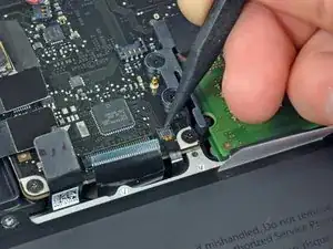
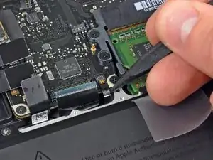
    • Wir empfehlen, vorsorglich den Akkuanschluss vom Logic Board zu lösen, um eine elektrische Entladung zu verhindern.

    • Löse mit der Kante eines Spudgers den Akkuanschluss nach oben, weg vom Sockel auf dem Logic Board.

    Zitat von gansodesoya:

    why is step 3 necessary?

    Just to disconnect any power source to avoid damages by short-circuits.

    MrKane -

    How do you get that battery connector back on? Do you just press it in back in place after you're done?

    Horace Chung -

    yes. I usually plug it in before I screw it down so I can lift the battery a bit and have enough slack to be able to go straight down on the connector, otherwise it comes in on a bit of an angle, which can't be good (though not necessarily bad).

    maccentric -

    This step almost finished me, and I did extensive damage to the battery plug. Fortunately, I later replaced the battery, and the replacement came with a new plug! :) Newbies need to know - 1. The battery plug is like a thin lip on a thicker lip, so you need to pry BETWEEN 2 thin lips to get it off, else you are trying to yank out the socket. 2. Mine was initially VERY tight, and trying to get it out broke the plastic on all sides of plug, even though I was as careful as possible. Luckily, this didn't hurt functionality and I later replaced the battery. AFTER disconnecting once, it was never so tight again,

    Jeff Diamond -

  4. oayXJg6IuMPTQyCH
    oayXJg6IuMPTQyCH
    WwrFHvUYBPYklZYx
    Hx6kNoL3Tll4qUlx
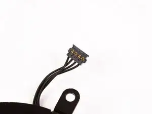
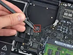
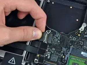
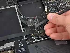
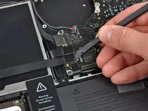
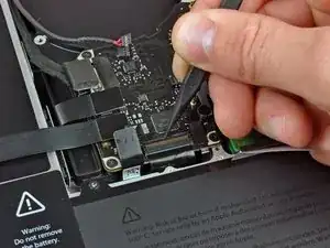
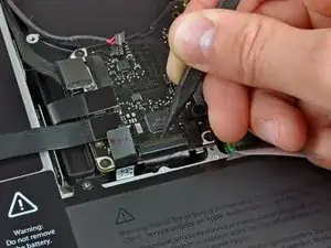
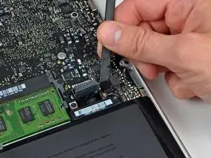
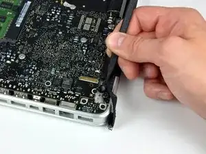
    • Hebele den Stecker des Lüfters mit einem Spudger aus seinem Sitz heraus und gerade weg vom Logic Board.

    • Am Besten kannst du den Stecker lösen, indem du den Spudger unter den Drähten zum Lüfter einsetzst und axial verdrehst.

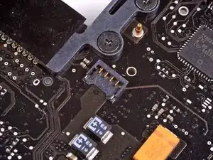
    • Im dritten Bild sind der Sockel und der Stecker des Lüfters zu sehen. Sei vorsichtig und breche nicht den Plastiksockel des Lüfters aus dem Logic Board, wenn du mit dem Spudger den Lüfterstecker gerade hoch und aus dem Sockel heraus hebst. Dein Logic Board sieht vielleicht etwas anders als im zweiten Bild aus, aber der Lüftersockel ist gleich.

    I just soldered it back on. . . I tried to clean the pads with braid first, but it didn't do much so I don't think that's necessary. I first supper-glued it in place with the pins on the pads and then I put a tiny dab of solder on each pin/pad. Plugged in the fan and i works!

    Ron Hudson -

    Just the answer I was looking for Ron! Awesome work buddy!

    lucasjmenzie -

    i recommend not to use the spudger. you damage more than by unpluggin the plug by hand. just simply pull the cable close to the plug of the old fan softly upwards out. the plug than comes easily out. put the new fan in and push the new plug by hand in. it is much easier than using a spudger. i also started with a spudger but nearly broke the plug out, so i watched a youtube tutorial and learned about it…

    andre -

  5. 3Nc1eu6YQ2EkLTyw
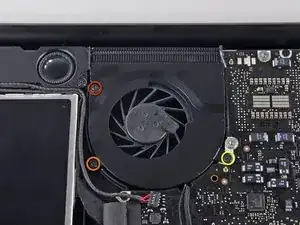
    • Entferne die folgenden drei Kreuzschlitzschrauben, welche den Lüfter am oberen Gehäuse befestigen:

    • Eine 6,5 mm Schraube

    • Eine 5,5 mm Schraube

    • Eine 4,5 mm Schraube

  6. PIOdxKZehcYT1lNG
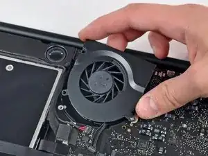
    • Hebe den Lüfter aus dem oberen Gehäuse.

  7. H5WoEX35nCJxJoVc
    H5WoEX35nCJxJoVc
    2h2sAVKwuSa6RdtP
    GOTxbmD6vWqqpGd3
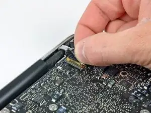
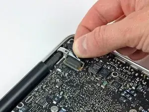
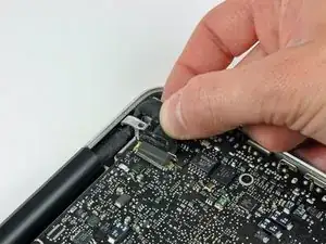
    • Fasse die Plastiklasche an, die am Sicherungsbügel des Displaydatenkabels befestigt ist, und drehe sie zur Seite des Computers mit der Gleichstromversorgung (DC-In) hin.

    • Ziehe den Stecker am Displaydatenkabel gerade aus seinem Sockel heraus in Richtung der Gleichstromversorgung (DC-In) des Computers.

  8. gQSfcvhCduWgFmTM
    gQSfcvhCduWgFmTM
    SepnYJ2fJKAXxapY
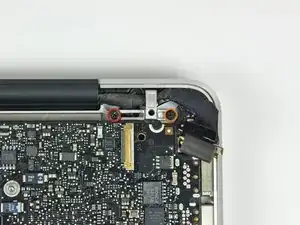
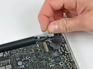
    • Entferne die folgenden beiden Kreuzschlitzschrauben, welche die Halterung des Displaydatenkabels am oberen Gehäuse befestigen:

    • Eine 7 mm Schraube

    • Eine 5 mm Schraube

    • Hebe die Halterung des Displaydatenkabels aus dem oberen Gehäuse.

    Mine are Torx and got an extra clamp for the cable, just above the left screw

    Martin -

    If you only want to replace the DC-in board, stop here and GOTO 17 (and DO NOT 4 and 6).

    When the Logic board is loose, lift it up on the Harddrive end and shift slightly towards the HD, so that the USB connectors at the outside come free from under the case rim and the board can be lifted up a bit. Then there´s enough room to move the DC in board, pull the cable out with a pair of tweezers, wriggle it out from under the microphone cable and wriggle the new connector in. It can be pushed into the socket with tweezers or a small screwdriver. This worked perfect for me.

    Be careful not to bend the logic board, but otherwise I think there´s much less risk of messing anything up with all the connectors and bits and pieces that need to be loosened and fastened.

    Mike -

  9. 5S2ufCCUjVZjRSVR
    • Hebele mit dem flachen Ende des Spudgers den Stecker von Subwoofer und rechtem Lautsprecher vom Logic Board hoch.

  10. U6VC4QVXgkmSKuKW
    • In diesem Schritt wird das Kamerakabel gelöst. Bei den meisten Geräten ist ein kleiner selbstklebender Halter am Logic Board angebracht, damit der Stecker festhält. Bevor du das Kabel entfernen kannst, muss der Halter aus dem Weg sein.

    • Ziehe den Stecker am Kamerakabel in Richtung des optischen Laufwerks, um es vom Logic Board zu trennen.

    • Der Sockel ist aus Metall und kann leicht verbogen werden. Richte den Stecker genau am Sockel aus, bevor du ihn wieder einsteckst.

    There is a small piece just below this connector which is just an adhesive block to keep the connector from coming out. It is easiest to peel it up first with a fingernail or spudger then remove the cable. Likewise reinsert the cable before reapplying the adhesive safety stop.

    Justin Jett -

    I couldn't reconnect this cable correctly, so my camera is not working anymore.

    It doesn't matter to me, I didn't used the camera that often...

    But the Ambient Light Sensor uses the camera to control keyboard lighting, so I wasn't able to see my keyboard in the dark anymore... :(

    If you have the same problem, after a couple of google hits I've found this app: https://www.macupdate.com/app/mac/22151/...

    Problem solved! YAY!

    PS: be careful because WIFI passes through this cable as well!!!!

    simbass -

    Look at the photo intently. The connector is inserting not in parallel, but at a slight angle. The bottom corner of the connector is slightly ahead. It is important! Singular metod to insert it.

    Vladimir -

  11. mpLOpCIkoW2xCqif
    mpLOpCIkoW2xCqif
    W2C43m61pZ6Dyqcb
    eo6LQDikRDMpITI5
    • Hebele die Stecker am Kabel vom optischen Laufwerk, der Festplatte und des Trackpads mit dem flachen Ende des Spudgers vom Logic Board hoch.

  12. 4Sf1wHms3aaL4MXg
    4Sf1wHms3aaL4MXg
    AE14gLXhNbiplKt4
    C1TOaQijIPD6LtQn
    • Klappe den Sicherungsbügel am ZIF Verbinder des Flachbandkabels zur Tastatur mit dem Fingernagel oder der Spudgerspitze hoch.

    • Schiebe das Flachbandkabel zur Tastatur mit dem Spudger aus seinem Sockel heraus.

    When reinserting the keyboard ribbon cable, make sure you push it in all the way (two plastic tools are helpful - one to push it down flat, the other to coax it all the way in). For 3 days after replacing a top case, my MacBook Pro 13" wouldn't start up. I thought the main logic board was fried too. However, reinserting the keyboard ribbon cable again, this time perhaps 1mm farther in, and it started up again! I did the same for the "keyboard backlight ribbon cable" (i.e. reinserted it just to make sure). Really not sure which completed the circuit so is would start, but I suspect the keyboard ribbon cable.

    amiller770 -

    Zitat von amiller770:

    When reinserting the keyboard ribbon cable, make sure you push it in all the way (two plastic tools are helpful - one to push it down flat, the other to coax it all the way in).

    I usually use a piece of sticky transparent office tape and stick it over the flat cable a bit further away from the mating part then pull on it. There is no better way to force the flat cable into a stiff connector without damaging the fragile cable.

    Leo Bodnar -

    As others have stated, if the keyboard ribbon cable isn't fully inserted the MBP will not power on. Leo Bodnar's recommendation to use a piece of transparent office tape did the trick for me. Many thanks Leo!

    Matthew Rankin -

    Inserting the ribbon cable for the keyboard was really difficult, but i was able to get it in using a piece of tape and pulling it up, just like the tape on the keyboard backlight.

    Kelly Legner -

    Using a piece of tape is sheer genius Kelly. My mom once said her definition of genius was an idea that, when you hear it, you say to yourself, “now why didn’t I think of that?” But you never would have thought of it. Brava (or bravo) Kelly!

    JonnyLine -

  13. ORKjULSYLhNuFQUi
    • Ziehe das kleine Stückchen schwarzes Klebeband vom Sockel des Flachbandkabels der Tastaturbeleuchtung ab.

  14. omJ1eHiMfXlFtGVO
    omJ1eHiMfXlFtGVO
    GGYWsYuMi5kZONiq
    TPaIFGAGOPyrUnkA
    • Klappe den Sicherungsbügel am ZIF Verbinder des Flachbandkabels der Tastaturbeleuchtung mit der Spudgerspitze hoch.

    • Schiebe das Flachbandkabel zur Tastaturbeleuchtung mit der Spudgerspitze aus seinem Sockel.

  15. cZ3jLTCybSZqjX1s
    • Hebele den Stecker am Kabel der Akkuanzeige mit dem flachen Ende des Spudgers vom Logic Board hoch.

  16. 1ttqGf15CrXqgESa
    • Hebele das Mikrofon mit der Spudgerspitze aus der Klebeverbindung zum oberen Gehäuse.

  17. hlvPHn5hLlwTnykQ
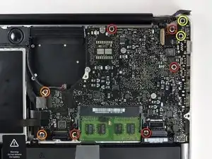
    • Entferne folgende Kreuzschlitzschrauben:

    • Fünf 3,1 mm Schrauben

    • Zwei 3,9 mm Schrauben

    • Zwei 7 mm Schrauben vom DC-In Board

  18. uqAscA6i2AwOjsxs
    uqAscA6i2AwOjsxs
    1FKTMO2VElhgwKAM
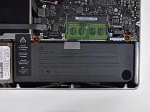
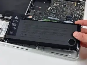
    • Entferne folgende Tri-point Schrauben, welche den Akku am oberen Gehäuse befestigen:

    • Eine 5,5 mm Schraube

    • Eine 13,5 mm Schraube

    • Hebe den Akku aus dem oberen Gehäuse.

  19. MWPHlxOjnkYSuqrw
    MWPHlxOjnkYSuqrw
    ZgwauAvagMTUNQWZ
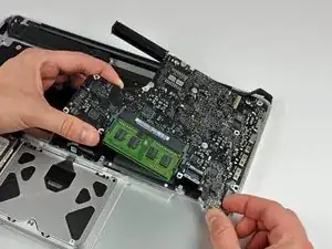
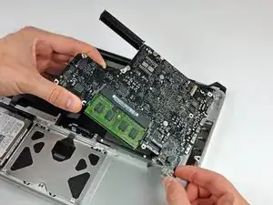
    • Hebe das Logic Board an der linken Kante hoch und ziehe weiter daran, bis die Anschlüsse an der Seite des oberen Gehäuses frei werden.

    • Ziehe das Logic Board von der Seite des oberen Gehäuses weg und entferne es. Achte dabei darauf, dass sich das DC-in Board nicht verfängt.

    • Sei vorsichtig und beschädige nicht den empfindlichen Stecker der Mikrofoneinheit.

    When putting the logic board back in place, it's easier to angle the mic down in it's place as you are placing the board in, rather than after the board is seated.

    amiller770 -

  20. xGyBjHOwQQdKoja5
    xGyBjHOwQQdKoja5
    ZdhJAH3BsrvYTWIX
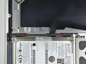
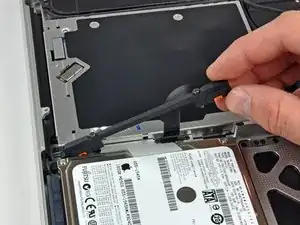
    • Entferne die beiden Kreuzschlitzschrauben, welche die Halterung der Festplatte am oberen Gehäuse befestigen.

    • Diese Schrauben bleiben in der Halterung hängen.

    • Hebe die Halterung aus dem oberen Gehäuse heraus.

  21. PJnoG6qwh5cGlgTO
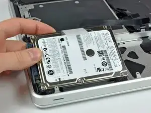
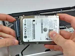
    • Hebe die Festplatte an ihrer freien Kante hoch und ziehe sie aus dem Rahmen heraus, denke dabei an die Kabel, mit denen sie noch an den Computer angeschlossen ist.

  22. cxWUEGYZqfFbFiHR
    • Ziehe den Stecker des Festplattenkabels von der Festplatte ab.

  23. rmdEJNDff64DZ62H
    rmdEJNDff64DZ62H
    orewaCNHDgjVfyLv
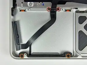
    • Entferne folgende vier Kreuzschlitzschrauben, welche das Festplatten- und Infrarotsensorkabel befestigen:

    • Zwei 1,5 mm Schrauben

    • Zwei 4 mm Schrauben

    • Schiebe die Halterung der Festplatte und des Infrarotsensors weg von der Kante des oberen Gehäuses.

    • Löse vorsichtig die Kabel von Festplatte und Infrarotsensor vom oberen Gehäuse ab.

  24. Va2qhZsyLNL1RFm4
    Va2qhZsyLNL1RFm4
    wLbEBcVRAR5cEIE4
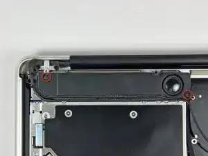
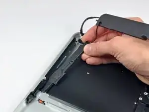
    • Entferne die beiden Kreuzschlitzschrauben, welche den Subwoofer am oberen Gehäuse befestigen.

    • Die längere (8,2 mm) der beiden Schrauben befindet sich rechts. Die kürzere der beiden (5 mm) ist links.

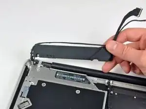
    • Der Subwoofer ist immer noch am rechten Lautsprecher angeschlossen, Versuche also nicht, ihn ganz zu entfernen.

    • Hebe den Subwoofer vom optischen Laufwerk weg und lege ihn über dem Computer ab.

  25. 1PWxVpasGMpJpUkk
    1PWxVpasGMpJpUkk
    eN1iJ2lPKPbTbk3f
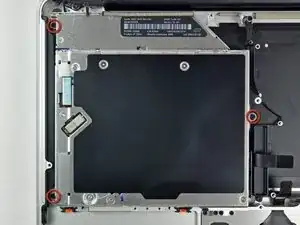
    • Entferne die beiden 9,2 mm Kreuzschlitzschrauben, welche die Halterung des Kamerakabels am oberen Gehäuse befestigen.

    • Die innerste Schraube kann im Kamerakabel hängen bleiben.

    • Wenn du das Mitte 2010 Modell hast, sieht die Halterung des Kamerakabels vielleicht etwas anders aus, das Verfahren ist aber das gleiche.

    • Hebe die Halterung des Kamerakabels aus dem oberen Gehäuse.

  26. SNHJiAx1GSqdkH4H
    SNHJiAx1GSqdkH4H
    wiUTVLYpJrmHQcdU
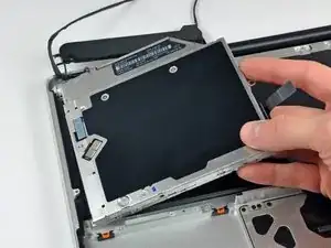
    • Entferne die drei 2,5 mm Kreuzschlitzschrauben, welche das optische Laufwerk am oberen Gehäuse befestigen.

    • Hebe das optische Laufwerk an der rechten Kante an und ziehe es aus dem Computer.

  27. y4MNPWHZHWjgFlaS
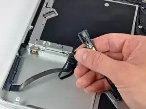
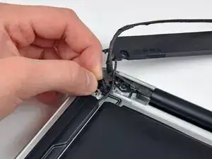
    • Ziehe das kleine Stückchen schwarzes Klebeband ab, welches das rechte Lautsprecherkabel bedeckt.

    • Sei vorsichtig, denn direkt unter diesem Stück Klebeband befindet sich das Flachbandkabel zur Einschalttaste

  28. byuyI5iDbyWovPYf
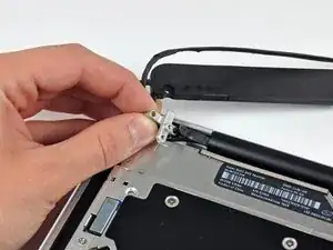
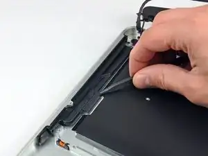
    • Hebele den rechten Lautsprecher mit der Spudgerspitze aus der Klebeverbindung zum oberen Gehäuse.

  29. Nf132Ihq3AGaHBpK
    • Hebe die Einheit aus Subwoofer und rechtem Lautsprecher aus dem oberen Gehäuse.

  30. dG4xpxG2pnAFVYQW
    dG4xpxG2pnAFVYQW
    6yKVIATpyNrdcRCb
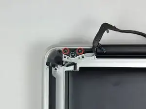
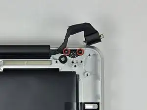
    • Entferne die beiden äußeren 6 mm Torx Schrauben, welche jede Seite der Displayhalterung am oberen Gehäuse sichern. (Also insgesamt vier Schrauben)

    • Beim Zusammenbau musst du die inneren 6 mm Torx Schrauben eine Viertel Umdrehung zurückdrehen, dann das Display und das obere Gehäuse vorsichtig ausrichten, bevor du die äußeren Torx Schrauben eindrehst. Wenn Display und Gehäuse gut ausgerichtet sind, ziehe erst die inneren Schrauben fest und setze dann die äußeren Schrauben ein und drehe sie fest.

    When re-assembling everything, you'll need to back out the inner screws a bit and align the upper case and display. After aligning them, tighten the inner screws again, then insert and tighten the outer screws.

    bradeyh -

  31. IShfrACxd6jSboxA
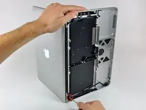
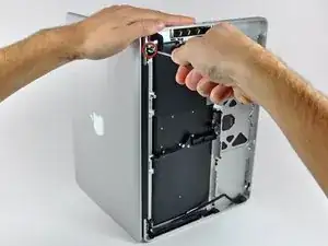
    • Öffne dein MacBook so, dass Display und oberes Gehäuse einen rechten Winkel bilden.

    • Stelle dein MacBook so wie gezeigt auf einen Tisch.

    • Halte das Display und das obere Gehäuse mit der linken Hand zusammen. Entferne dann die 6 mm Torx Schraube von der unteren Displayhalterung.

  32. BCZbyS2nOOk1w52i
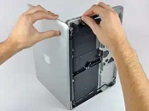
    • Halte das Display und das obere Gehäuse gut mit der linken Hand zusammen. Wenn du dabei einen Fehler machst und es loslässt, kann dein Display/oberes Gehäuse herunterfallen und dabei jedes Bauteil beschädigt werden.

    • Entferne die letzte verbleibende 6 mm Torx Schraube, die das Display am oberen Gehäuse befestigt.

  33. YOsEAp3oxLNseANa
    YOsEAp3oxLNseANa
    FUTJUZDFDHM2wXLO
    JeNqIE2TKeWMcO5v
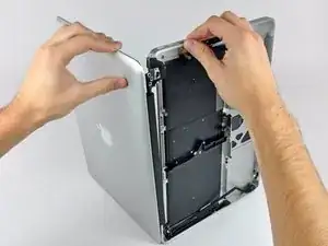
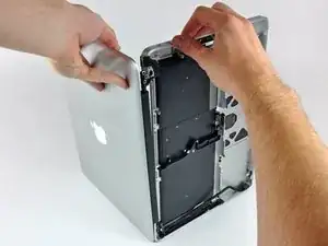
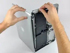
    • Fasse das obere Gehäuse mit der rechten Hand und drehe es leicht in Richtung Oberkante des Displays, so dass die obere Displayhalterung von der Kante des oberen Gehäuses frei kommt.

    • Drehe das Display etwas weg vom oberen Gehäuse.

    • Hebe das Display hoch und weg vom oberen Gehäuse, achte dabei darauf, dass sich keine Halterungen oder Kabel verfangen.

Abschluss

Um dein Gerät wieder zusammenzusetzen, folge den Schritten in umgekehrter Reihenfolge.
Walter Galan

685540 Reputation

0 Kommentare