Einleitung

  1. HMAf24Ge5JeKjrXC
    HMAf24Ge5JeKjrXC
    vcDy4UyFxXCqSMbd
    LoZj4jgRQpnOPEyA
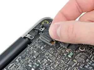
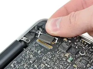
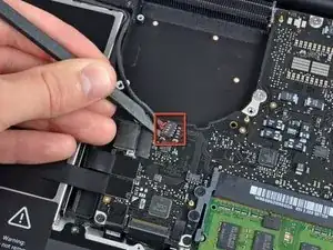
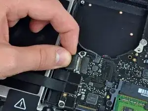
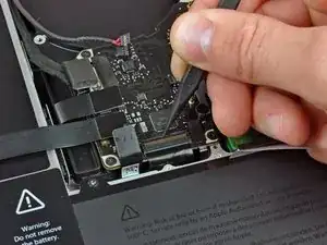
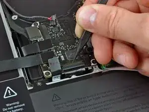
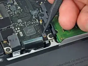
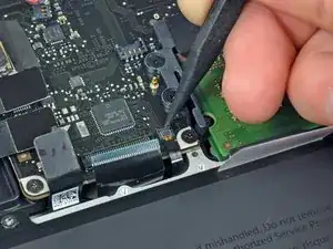
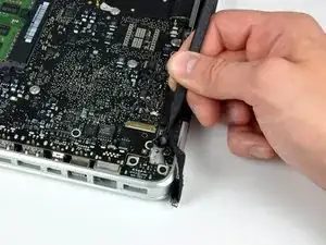
    • Fasse die Zuglasche am Sicherungsbügel des Display-Datenkabels an und drehe es in Richtung der Seite mit DC-in Buchse.

    • Ziehe den Verbinder des Display-Datenkabels vorsichtig direkt aus seinem Sockel heraus, parallel zum Logic Board.

    • Ziehe das Kabel nicht nach oben, damit könntest den Anschluss kaputt machen.

    On my system the pad on top of the connector was shifted making the bracket difficult to rotate into the up position. The bracket looks like a handle so my first instinct was to pull it straight up. Big mistake. I ended up popping the brass guard off the connector on the logic board. The instructions could benefit from an arrow indicating the direction to pull and rotation of the bracket.

    highnoontoday -

  2. quIfTtoLygA1pOSJ
    quIfTtoLygA1pOSJ
    RUyjCQiOXECuiTPC
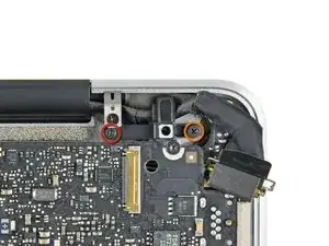
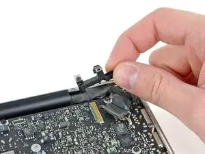
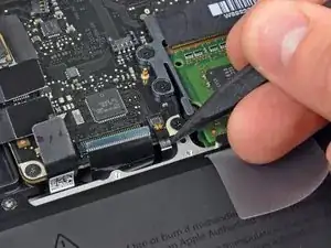
    • Drehe folgende Kreuzschlitzschrauben heraus, die die Befestigungsklammer des Display-Datenkabels am Gehäuse sichern:

    • Eine 8,6 mm Kreuzschlitzschraube

    • Eine 5,6 mm Kreuzschlitzschraube

    • Hebe die Klammer des Display-Datenkabels aus dem Gehäuse.

  3. 2pApI4moCDTnBuaR
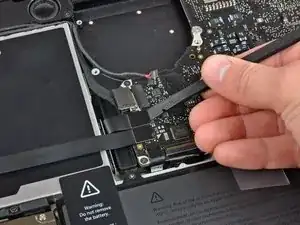
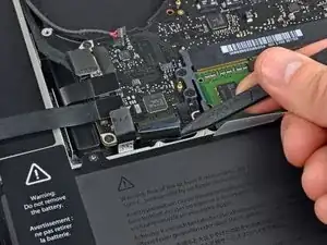
    • Heble die Verbinder vom Subwoofer und rechten Lautsprecher mit dem flachen Ende eines Spudgers vom Logic Board.

    Push it straight down. It should snap in.

    BobG -

    The first time i tried this on a MBP 13 I broke the connector form the board. It should be noted that you have to be very careful in this step, as the plug fits very tightly and you can easily use too much force to tear the connector from the board. Use a second spudger to hold down the connector at its border and try very gently using a second spudger to move the plug out of the connector upwards.

    Joachim Kathmann -

  4. eT5TmcDL5Qy5VvaZ
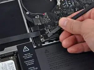
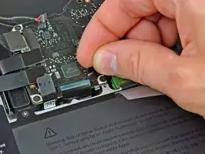
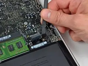
    • Ziehe den Stecker des Kamerakabels in die Richtung des optischen Laufwerks, um es vom Logic Board zu trennen.

    • Dieser Anschluss ist aus Metall und verbiegt sich leicht. Achte darauf, den Stecker und den Anschluss auf dem Logic Board zueinander auszurichten, bevor du die beiden Teile miteinander verbindest.

    As mentioned, the socket can be easily damaged when re-inserting it. I didn't care enough and one pin was damaged. Wifi was not detected.

    Hopefully the pin was not broken (only bent). Putting it back in its correct position, the wifi re-appeared.

    Arnaud ROSAY -

  5. wQtcOZqJFEcMuscb
    wQtcOZqJFEcMuscb
    MXnNM5NWNiSECMb2
    IKTPRlkXrAeF1BDD
    • Heble die Verbinder vom optischen Laufwerk, von der Festplatte und vom Trackpad mit dem flachen Ende eines Spudgers vom Logic Board.

  6. NCikjBxhaHd3CiRb
    NCikjBxhaHd3CiRb
    w1JBbMoOZJu6bgJD
    YyJRXXLQCKhgO3CP
    • Hebe die Sicherungsklappe am ZIF-Verbinder für das Flachbandkabel der Tastatur mit dem Fingernagel oder einer Spudgerspitze hoch.

    • Schiebe dann mit dem Spudger das Flachbandkabel der Tastatur aus dem Sockel.

    Sometimes spulger is not the best tool to slide the cable out. If it is difficult to slide, try two toothpicks to pull the cable from two sides simultaneosly.

    Leo Nikitin -

    Toothpicks did the trick, thanks

    Gábor SEBESTYÉN -

    As Mateo said, replacing the zif cable is NOT easy, and in this case, will leave you with a computer that won't power on- this cable connects the power button. I learned a trick somewhere for dealing with these cables- put a piece of good sticky tape on the cable, and use it to pull it back into the connector. Works every time.

    stevesontheroad -

    Yeah! The tape trick worked for me. Thanks!

    Ted Bishop -

    Thank you Steve, it’s works perfectly.

    never_forever18 -

  7. xakWmCBC3OMuMyXe
    • Ziehe das kleine Stück schwarzes Band vom Sockel des Flachbandkabels der Tastaturbeleuchtung ab.

    Be very careful while taking this black tape off. I accidentally broke the chip off the motherboard and so my keyboard is not backlit any more.

    Asim Akath -

  8. kMZTPOCecXPuvVLW
    kMZTPOCecXPuvVLW
    jJjWXgvVBQ1nhNR1
    qJl2UwjCZQndDIOF
    • Hebe die Sicherungsklappe am ZIF-Verbinder für das Flachbandkabel der Tastaturbeleuchtung mit der Spudgerspitze hoch.

    • Schiebe dann mit dem Spudger das Flachbandkabel der Tastaturbeleuchtung aus dem Sockel.

    Be especially careful as my hole socket detached from the board. It would have helped to vertically press the socket to the board with the tip of a spudger. Thus partially blocking the strap, you can first peel the free end, then change position and peel the rest. Slide the ribbon cable perfectly horizontally.

    Rainer -

    I had the same issue of trying to get the ZIF cable back in but found that if I used a piece of scotch tape, it worked. I followed this guide. MacBook unibody keyboard ribbon cable won't go in

    spearson -

    A reassembly trick that works for me is to use some 3/4" blue painters tape to stick to the very back (lower end) of the ribbon cable so I can pull it up and back before locking the cam. Trying to get a good grip without cutting, or crimping the ribbon means no tweezers or pliers can be used.

    originalmachead -

  9. GA4R6Z1udiBdAWjp
    • Heble den Verbinder des Kabels der Akkuanzeige mit dem flachen Ende des Spudgers aus dem Logic Board.

    If you’re swapping top cases, you might need to remove the battery indicator from the case and swap it to the replacement top case. It attaches with three very tiny Phillips screws. I wasn’t aware that my replacement top case didn’t have this part and got confused when reversing the steps to reassemble and I didn’t have this connector. I had to take the battery back out in order to swap the indicator over.

    Mark Barnes -

    Interesting this guide doesn’t have you disconnect the battery after step 2 then shows it unplugged already in step 14.

    plink53 -

    I would recommend revision to this guide to put battery disconnection as the first step after opening the bottom case. First rule of logic/mother boards: don’t work on or around if power is applied.

    dsfeehan -

  10. 5acPEhbAXlAZMqvR
    • Löse die Klebeverbindung des Mikrofons am oberen Gehäuse mit der Spudgerspitze.

    on the Australian/Asia version speaker cable is located underneath the logic board.

    linuxuser101 -

  11. pUjsTWMyb1uXYtmK
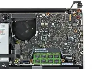
    • Entferne folgende Torx-Schrauben:

    • Zwei 7mm T6 Torx Schrauben an der DC-in Platine.

    • Fünf 3,3 mm T6 Torx Schrauben

    • Zwei 4 mm T6 Schrauben

  12. 1VTxI1RA5d52tAWU
    1VTxI1RA5d52tAWU
    WFrYefLTAEXc5BJN
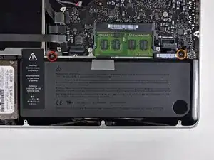
    • Es ist nicht zwingend nötig den Akku zu entfernen, bevor du das Logic Board heraushebst. Es ist aber sicherer und einfacher. Wenn du den Akku drinnen lässt, achte sehr darauf, dass du das Logic Board nicht am Akku in der Nähe des Strichcodes verbiegst.

    • Entferne folgende TriPoint Schrauben, die den Akku am oberen Gehäuse befestigen:

    • Eine 5,5 mm TriPoint Schraube

    • Eine 13,5 mm TriPoint Schraube

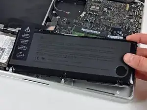
    • Hebe den Akku aus dem Gehäuse.

  13. dcGNaBIhDMgYwwJJ
    dcGNaBIhDMgYwwJJ
    2fc6NewMHSOyvrAg
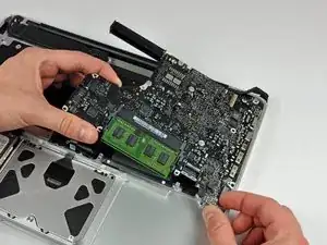
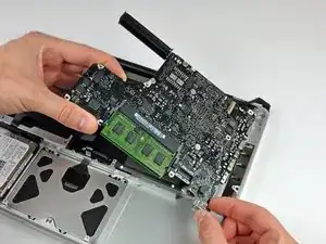
    • Hebe das Logic Board am linken Rand hoch, bis die Ports aus der Seite des oberen Gehäuses frei werden.

    • Ziehe das Logic Board von der Seite des Gehäuses weg, achte dabei darauf, dass sich die DC-in Platine nicht verfängt.

    Be careful while taking the board out, as the heatsink usually is caught by the optic drive.

    Leo Nikitin -

    mid 2012: Careful of the left speaker (on your right because unit is upside down). Gently remove with spudger tool before removing logic board and when reinstalling press firmly back into place with spudger. Install speaker after putting logic board in place but before installing screws.

    JASON CULP -

    Step 18 is out of order. Steps following this show it still installed, which is confusing.

    plink53 -

Abschluss

Um dein Gerät wieder zusammenzusetzen, folge den Schritten in umgekehrter Reihenfolge.
Walter Galan

685541 Reputation

0 Kommentare