Einleitung

Voraussetzung beim Ausbau des Logic Boards

  1. ABFQ1yWISq4jrhaR
    ABFQ1yWISq4jrhaR
    LXxAYFsXXuUcyCRY
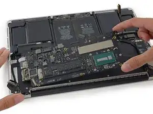
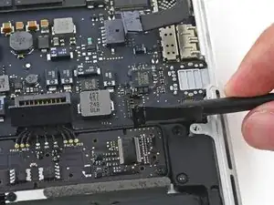
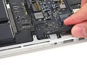
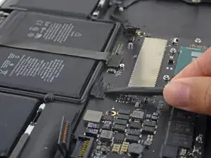
    • Entferne die beiden 2,1 mm Torx T5 Schrauben, welche die Halterung des Kabels zur I/O Karte am Logic Board befestigen.

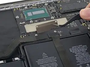
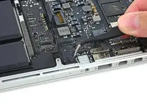
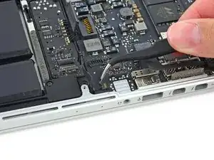
    • Entferne die Halterung des Kabels zur I/O Karte.

  2. SkY3xXSaxDYURa6s
    SkY3xXSaxDYURa6s
    yGefv5CEUndfydC2
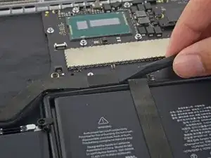
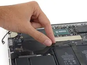
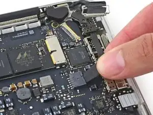
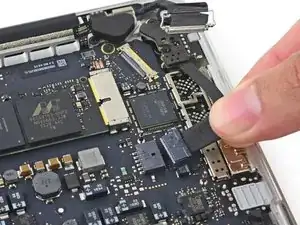
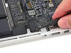
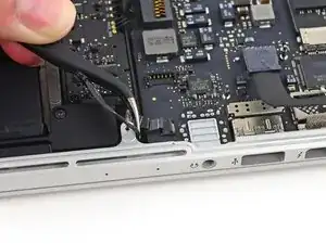
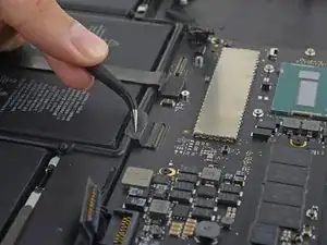
    • Lasse den Stecker der I/O Karte mit dem flachen Ende des Spudgers gerade aus seinem Sockel auf dem Logic Board herausspringen.

    • Achte darauf, dass du nur am Stecker hebelst, nicht am Sockel selbst. Du riskierst sonst, dein Logic Board zu beschädigen.

  3. oGEMhZLIK5WNXDhN
    oGEMhZLIK5WNXDhN
    MCuqWkbPcZja4hs2
    • Hebe das I/O Board Kabel an der Logic Board Seite hoch, um es aus dem Weg zu biegen.

    • Falte das Kabel nur an der gebogenen Stelle am Ende nahe der I/O Karte, damit es keinen Schaden nimmt.

  4. DLAVERplRRgdAZsA
    DLAVERplRRgdAZsA
    5GxblI3unIyoHfZO
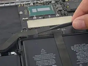
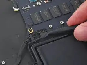
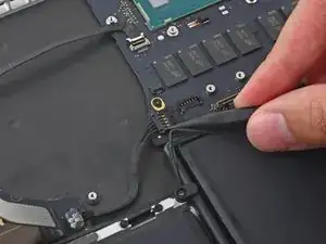
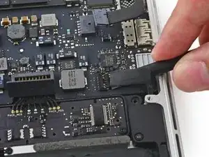
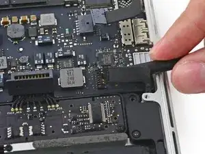
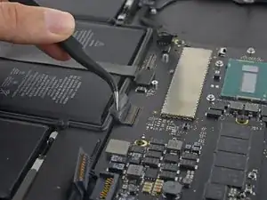
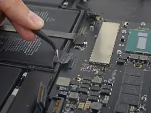
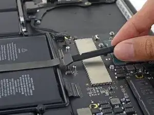
    • Hebe den Stecker zum rechten Lautsprecher mit der Spudgerspitze gerade aus seinem Anschluss auf dem Logic Board.

  5. ZLy5bVJMmnmMBA1a
    ZLy5bVJMmnmMBA1a
    pPIGxhBXGEwSQeOK
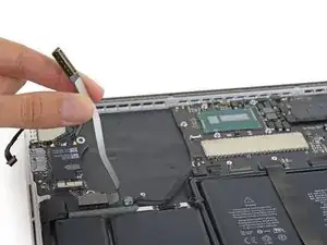
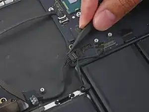
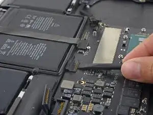
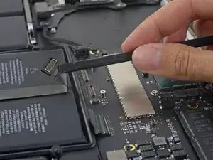
    • Drücke abwechselnd mit der Spudgerspitze auf beiden Seiten des Steckers der I/O Karte, um ihn so aus seinem Anschluss auf dem Logic Board herauswandern zu lassen.

  6. qdoImI2Rmpwv5ncn
    qdoImI2Rmpwv5ncn
    EBacf5TjDUNj6vZP
    rkvWdkm6i3s1QaCc
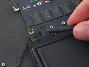
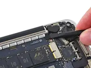
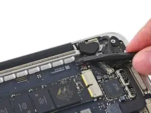
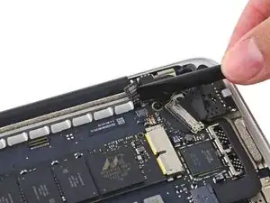
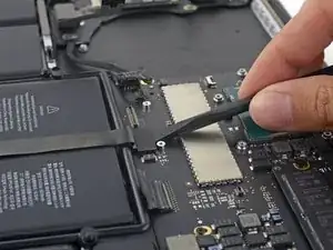
    • Löse das Kabel der Tastaturbeleuchtung mit dem flachen Ende des Spudgers und biege es nach oben, so dass der Weg zum Logic Board frei wird.

  7. XeiWdaL1f2FP132i
    XeiWdaL1f2FP132i
    jQT2pvbYI1tsTQJg
    o3byaKcGA1GtsiRp
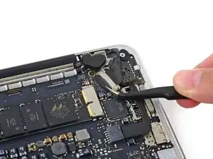
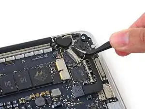
    • Fasse die schwarze Plastiklasche und klappe den Displaykabelstecker auf. Ziehe ihn dann gerade aus seinem Anschluss auf dem Logic Board heraus.

    In my 2015 retina MacBook Pro 13”: I saw as shown the piece of black plastic tape. One peels this off as shown, using the same tweezers shown, or something else. The tweezers shown work well to lift the stainless steel clip, again as shown. But I add here that the points of the ribbon cable to grab and pull horizontally back are not optimal, as shown. You do not have to grab the ribbon. There are two points where the wire clip attaches to the connector that work well as places to grab with the tweezers shown. Hope this is clear

    Thomas Sturgill -

  8. NHisJdNetFkCKeCk
    NHisJdNetFkCKeCk
    pxvgGOuFktkYGZQH
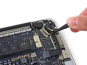
    • Ziehe vorsichtig den Stecker zur Platine der Gleichstromversorgung (DC-In) aus seinem Sockel auf dem Logic Board.

  9. gEmGsmZpKdLvw5Vu
    gEmGsmZpKdLvw5Vu
    RiCbA3F2sU12irKq
    cFfpTKhvmsOEMiiP
    • Zwänge das flache Ende des Spudgers unter das Kabel zum linken Lautsprecher nahe am Stecker und hebe es gerade aus seinem Sockel. Biege es dann aus dem Weg.

    I wasn’t careful enough or something, the socket came straight off, ouch. I don’t even see how it was connected originally. Not soldered or anything, will try to solder myself but it looks very thin. Be careful!

    Ray Dai -

  10. NFaffPxDVL6qRpj1
    NFaffPxDVL6qRpj1
    Jpm4GZRUnG6wvpER
    • Falls nötig, musst du jegliches Klebeband abziehen, welches den ZIF Verbinder am Mikrofonkabel bedeckt.

  11. RnGP5ACO4KHYg2oY
    RnGP5ACO4KHYg2oY
    qKeyNJaFOnRIv2BO
    qwgGhebiJSSRSmSj
    • Klappe den Sicherungsbügel am ZIF Verbinder des Mikrofonkabels mit der Spudgerspitze hoch.

    • Ziehe das Mikrofonkabel aus seinem Anschluss auf dem Logic Board.

    This tiny connector was difficult for me, and I hope I have not damaged it. Same design as some connectors already removed. A tiny, plastic front latch is lifted up, causing release. You grab the ribbon cable and pull it back horizontally, and to my surprise, this is end is just one tiny flat metal end, no multiple wire connectors that mate on the male end of the ribbon cable.

    Thomas Sturgill -

  12. 4IIPAEXtJP3i2UoB
    4IIPAEXtJP3i2UoB
    rHrjJZ532AdvYHyL
    xgAPI3TFRgCnQbTl
    • Falls nötig, musst du jegliches Klebeband abziehen, welches den Stecker am Tastaturkabel bedeckt.

    • Klappe den Sicherungsbügel am ZIF Verbinder mit der Spudgerspitze hoch.

    Also very difficult, because there is so little room to wriggle the ribbon cable, horizontally and backward. The photos do not offer a solution. The points I used are white (at least not black) points on the both, outer edges, and I was able to push there with the tip of the spudger.

    Thomas Sturgill -

  13. hF6VSPUSRrrE2DED
    hF6VSPUSRrrE2DED
    oC1yURZJ5qtOsZAc
    • Ziehe das Tastaturkabel gerade aus seinem ZIF Anschluss auf dem Logic Board.

  14. 24EJpuj2N4PhOAkj
    24EJpuj2N4PhOAkj
    SOd1kigaKCdQOwor
    fu4diPETjfZdbOlM
    • Lasse den Stecker vom Trackpad mit dem flachen Ende des Spudgers gerade aus seinem Anschluss auf dem Logic Board herausspringen.

    • Biege das Kabel über den Akku zurück, um den Weg für das Logic Board frei zu machen.

  15. fZHlMagfitKmnHmV
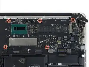
    • Entferne die fünf 3,5 mm Torx T5 Schrauben, welche das Logic Board am oberen Gehäuse befestigen.

    Il y en a une plus longue que les autres.

    Easy Repair -

  16. HLVhleSEEOJBY2xn
    HLVhleSEEOJBY2xn
    gFbCXM5lIgdaEWws
    6Af4XmKWPFl6cVEs
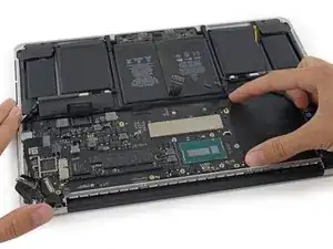
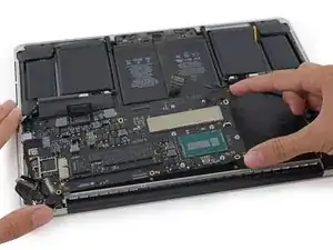
    • Hebe das Logic Board am Prozessorende etwas hoch und ziehe es in Richtung der Vertiefung für den Lüfter. So kommen die Anschlüsse an der Kante zum oberen Gehäuse frei.

    • Entferne das Logic Board.

    It won't come off; help!

    Zelma Garza -

    It seems to be stuck on the thunderbolt ports for me won’t come out

    Brendan O'Rourk -

    i found that it was difficult to get the processor back inside correctly during reassembly. it might take a few tries, as there are small “bracket” type pieces on the underside of the i/o ports that may bend out of shape. use caution, be exceedingly gentle and patient, but don’t give up!

    Colleen V -

Abschluss

Um dein Gerät wieder zusammenzusetzen, folge den Schritten in umgekehrter Reihenfolge.

Sam Goldheart

Mitglied seit: 19/10/12

457712 Reputation

0 Kommentare