Einleitung
Grundständige Anleitung
Werkzeuge
-
-
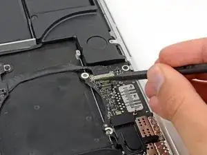
Verwende die Spitze eines Spudgers, um den Verschluss des I/O-Board Datenkabels nach oben zu klappen und es Richtung Akku zu drehen.
-
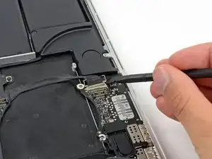
Verwende das flache Ende eines Spudgers, um das Datenkabel des I/O-Boards aus seiner Buchse auf dem Logic Board herauszuziehen.
-
-
-
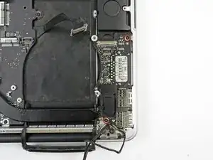
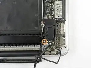
Entferne die beiden 3,1 mm T5 Torx-Schrauben, mit denen das I/O Board am Logic Board befestigt ist.
-
Bei manchen Modellen hilft es beim Ausbau des I/O Boards zusätzlich, wenn du auch die silberne 3,5 mm Torx T5 Schraube vom Kühlkörper entfernst.
-
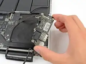
Hebe das I/O Board vorsichtig an und entferne es aus dem unteren Gehäuse.
-
Abschluss
Arbeite die Schritte in umgekehrter Reihenfolge ab, um dein Gerät wieder zusammenzubauen.


This is a difficult step. A few images for the removal of the cable would be good/better
Robert Jan Lebbink -
Yes, a few more detailed pics here would help. Indeed, general pics explaining HOW ALL the plugs and sockets fit would be VERY handy :-)
Simon Anthony -
Here is that guide!
Carsten Frauenheim -
I helped me to use the pliers both to get underneath the canble lock and then push on the wings of the cable.
Calvin Truong -
Used fingers on the cable lock.
Joseph Gorse -
gently use tips of tweezers at either side to walk it out
Christa -
It is much more easy to do step 21 before step 20 - this cable is more easy to remove
Also if you assemble then do step 20 before step 21 - it is more easy to place the cable into the connector
Muescha -