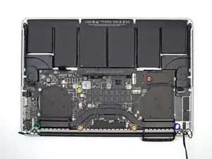
Einleitung

Grundständige Anleitung.

  1. kwyXuMVnFWtCSZKu
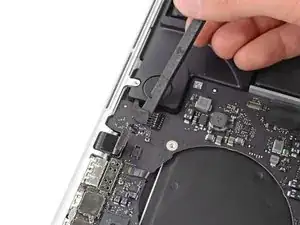
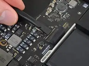
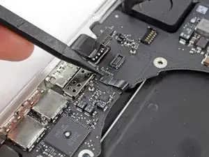
    • Verwende das flache Ende eines Spudgers, um die Kopfhörerbuchse von ihrem Anschluss auf dem Logic Board nach oben abzuziehen.

    After connect the cable aux is not working

    deepak selvanathan -

    Mine is not working as well after reconnecting, what to do now?

    Guillermo Pichardo -

    Strange, I'm working on the same model, and it doesn't have a flex here. It's soldered.

    Ross Karnes -

    Same as Ross. No cable to pry. It’s soldered. But looks like I can continue on anyway

    Cameron Melvin -

    Mine not soldered.

    Paul Clarke -

  2. 3NcryXfiewPjLtdx
    3NcryXfiewPjLtdx
    FrAmU6eUJuptE4yD
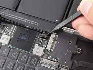
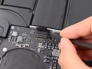
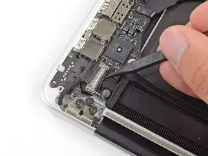
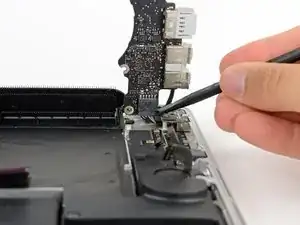
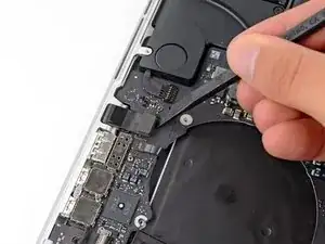
    • Verwende das flache Ende eines Spudgers, um den linken Lautsprecheranschluss aus seiner Buchse auf dem Logic Board herauszuziehen.

    • Benutze die Spitze eines Spudgers, um den rechten Lautsprecheranschluss aus seiner Buchse auf dem Logic Board herauszuziehen.

    • Achte darauf, dass du auch wirklich am Ende des Kabels ziehst, und nicht an der Buchse selbst. Wenn du den Hebel an der Buchse ansetzt, kann diese sich vom Logic Board lösen.

    This step could use an image showing the cable lock in the "up" position, releasing the connector. It is hard to see how it works in the "down" position. I think this is the actual connector - there are images in the PDF linked here:

    http://www.ddknet.co.jp/English/products...

    My MBP has an intermittent connection in this keyboard cable. It would be good to know where to buy a replacement!

    Rich -

    Pry the speaker connectors *up and out*. Doing it from the cable's sides, next to connectors, is easier.

    Kitipong Mork -

    Not sure what happened, but when I put it back together, i barely had enough room to plug this back in. It’s like the cable shrunk. I had to really yank on it to get it to fit.

    Jer -

    Adhesive under the left cable made it hard for me to remove it. The right one came out very easy.

    Calvin Truong -

    i broke off all the connectors to the logic board any fix for this ?

    Steven Rai -

    be gentle - lever under each edge of the connector - you may have to do one side then the other , but the connectors come out easily enough

    AES -

    Key here is to go EXTREMELY slow and gentle. The speaker connector in left photo has no release lever(in case you were wondering) I used a tweezer to hold very outside edge down while massaging cable side from underneath with spooner. Gentle rocking and it finally came out properly!

    Edward Bannan -

    These instructions are completely inadequate. For anyone who hasn’t done this before, there has to be some image of whatever it is that releases the cables. “Pry the left speaker connector up” without showing the release is just telling me how to turn my computer into junk. . . Which I just did. It’s twelve years old and fully backed up, so I was prepared for this, but I am very disappointed in these instructions. They’ve been bad from the start.

    David Ericksen -

    Es wäre besser, wenn man den Ausbau des rechten Lautsprecherkabels besser heraushebt! Ich habe das leider überlesen und den Connector zerstört. Aber ich habe es doch irgendwie geschafft, das der Lautsprecher funktioniert!

    markus.scheiner -

    Pay attention that there are 2 connectors of speakers! Otherwise, you will realise in step 32 (like I did) that you forgot one of them ;).

    Francisco Daza -

    Despite being extremely careful, both of these connectors broke off from their position on the logic board. It seems like they were soldered on rather than being just a push fit.

    Dave Harper -

    following these instructions exactly removed the entire socket from the board. This needs much more detailed instructions and pictures on how to accomplish this and how the connector is put together. the wide view here is grossly inadequate. This needs a much bigger warning to slide the cable away from the connector as any prying will destroy it. The socket came up and took the pads with it, so there's no soldering it back on. guess I'll just have to go without one audio channel in the onboard speakers

    Manuka -

    On minute 15:04, in this video, this step is better explained: https://youtu.be/ykqJenHhZJs

    amanda -

    well, i managed to do it without screwing the cable, you've actually got to hold the cables at the very base of their connection to the board and gently pull the all together up, not to the side.

    amanda -

  3. iGImQq1nGe5YUKis
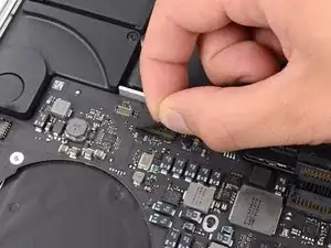
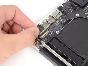
    • Wenn sich Klebeband auf dem Stecker des Tastatur-Flachbandkabels befindet, dann ziehe es davon ab.

    On Re-assembly, I found this to be the hardest part. I resorted to using the provided tweezers and taking turns left and right, working it back into its ZIF socket. If someone knows a better way, please share.

    Fred Anderson -

    I just got done with this and my plus/equal, tilde/apostraphe, brackets/braces and volume up keys are not working. Wondering is this isn't seated correctly or if i damaged something. :-(

    sturmjonny -

    This is one of the fussier flex cables to reconnect. I'd say it's worth opening it back up and reseating it. Only takes a few minutes—just disconnect the battery and then come straight to this step. Make sure the cable contacts are clean (wipe them with a little isopropyl alcohol and a lint-free cloth), and that the connector is clear of any dirt/debris (give it a good blast or two with some compressed air). Make sure the cable is inserted perfectly flat and straight into the connector (this is the hardest part, just takes patience and a little dexterity). Good luck!

    Jeff Suovanen -

    After replacing the battery I also ended up with keys that don't work (ESC, 0, -, p, ;, ', ENTER). Tried reseating the connector, but without any luck. What is weird is that the keys sometimes work, sometimes they don't. Usually they don't in the first 10 minutes or so after I turn on the mac. If the room temperature is lower (if it's cold), the keys are not functional for a longer period of time...

    Advice for other people who are changing their macbook battery: take extra care with this connector!

    alin.catana -

    This is really a pain to pull out. You sorta have to lift it up and out - I was worried I was going to flex the cable and break it too much.

    Jer -

    Use the retaining flap to pull the ribbon cable back into the socket.

    Andrew Dunning -

    This keyboard ribbon is so thin. It is like thinner than X-ray film. I was afraid to remove the ribbon from the socket. So, I skipped this step and follow other steps till ‘Step 30’. I didn't remove the logic board as shown in Step 31 and 32. Instead, I removed DC board screws and then DC board from the hole. The cable from the DC board connected at bottom corner of the logic board. I hold the MacBook Pro vertically and lift the logic board slightly and removed the DC board ‘plug’ from the socket. Next, I plugged in the new DC board and followed this procedure in reverse order ( from Step 30 to Step 1). Everything went fine. Important Note: When lifting logic board, please do it carefully and very slowly. Don’t be hurry and don’t break anything. Use magnifying glass and Magnifier in your iPhone to see the tiny parts big and clearly, before removing them.

    Jay Rajamanickam -

  4. igNuw2smaQPfTiHI
    igNuw2smaQPfTiHI
    N2XJmrDfDjQS4OJT
    wCbinbOGYupmVNWu
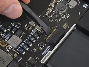
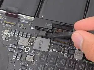
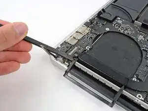
    • Klappe den Sicherungsbügel am ZIF-Anschluss des Flachbandkabels der Tastatur mit dem flachen Ende des Spudgers hoch.

    • Vergewissere dich, dass du den Spudger nicht am Anschluss, sondern nur am Sicherungsbügel ansetzt.

    • Ziehe das Tastatur-Flachbandkabel mit dem flachen Ende des Spudgers aus dem Anschluss heraus. Drücke erst auf einer, dann auf der anderen Seite.

    What is the connector to the right of the keyboard (shown in the above diagram i.e with battery at the bottom)?

    There doesn’t seem to be anything attached to this connector on my system.

    The trackpad connector looks quite similar to the leftof thekeyboard connector.

    Darrell Haslam -

    It connects to the EFI Chip.. You can read / write bios information here with dedicatet tools..

    smirgle -

    I was having trouble seating the keyboard connection back in. In actuality the issue was the real electronic connector was hidden under logic board after reinstalling the PCB! i was trying to insert the Tape cover instead! Had to re-loosen Logic board and retrieve connector (should see metal traces on the connection strip (that is an easy way to confirm! I had used some scotch tape to hold the cover tape back and this caused me to miss the actual wire harness! I advise anyone doing this process to have a magnifyer with a light so it is easier to see the small parts.

    Edward Bannan -

    Rather than pushing with the Spudger, I found it much easier to use the tape to pull directly back on the connector.

    Michael Bryenton -

  5. mhkqUcNS4FXD4ofs
    • Verwende das flache Ende eines Spudgers, um den Anschluss des Trackpad-Flachbandkabels von seiner Buchse auf dem Logic Board zu hebeln.

  6. YQo2PkxbsY3DEXQI
    • Verwende das flache Ende eines Spudgers, um den Anschluss für die Hintergrundbeleuchtung der Tastatur von seiner Buchse auf dem Logic Board nach oben abzuziehen.

    As with all the cables you must be careful here. This one felt even more fragile than the others to me.

    zacz0007 -

  7. GeUBqZobymBF5UUB
    • Klappe mit der Spitze eines Spudgers oder mit deinem Fingernagel die Halteklappe an der ZIF-Buchse des Mikrofon-Flachbandkabels nach oben.

    • Vergewissere dich, dass du den Hebel auch wirklich an der Halteklappe ansetzt und nicht etwa an der Buchse selbst.

    • Ziehe das Mikrofon-Flachbandkabel aus seiner Buchse.

    A small elastic popped out when removing the cable. Glad I wore the protective glasses.

    Louie -

    Meaning, pull the ribbon cable out horizontally. And be aware that the copper wiring is on the underside of the cable and the topside is just black plastic, so don’t freak out and think you ripped something pulling it out.

    Chapman Harrison -

    This cable is quite stiff and felt very resistant to being pulled out - I gently shaped a small bread tag piece of plastic in to a hook that would gently and evenly pull the cable back without tilting it to one side or the other. It is also a pain getting it back in when replacing the logic board - very stiff. Be patient.

    AES -

    I just used tweezers.

    curtis phan -

    Looks like it had a sticky patch fixing it near the edge of the board - this would make it unwilling to come out of the socket. The patch looks to be the width of the cable and square, so probably pushing a thin something (plastic) under the cable up to the edge of the board would unstick it.

    Christopher -

  8. TwIELCp3mYRYmnyZ
    TwIELCp3mYRYmnyZ
    dh15WV5WJdVcDo6J
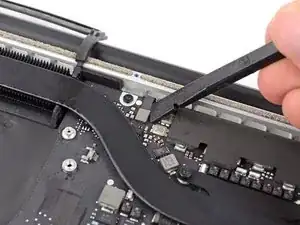
    • Benutze die Spitze eines Spudgers, um den Verschluss des Display Datenkabels zu lösen und drehe es in Richtung des DC-In.

    • Ziehe das Display Datenkabel aus seiner Buchse auf dem Logic Board heraus.

    • Hebe das Display Datenkabel nicht an, da dessen Buchse sehr empfindlich ist. Ziehe das Kabel parallel zur Stirnseite des Logic Boards ab.

    I'd recommend using the pliers.

    Calvin Truong -

  9. 2RRpi2HU4TB5b6LI
    • Verwende das flache Ende eines Spudgers, um vorsichtig die Gummikappe der Linsenschraube in der Nähe des MagSafe 2-Steckers abzuhebeln.

  10. LRIouFU1vREQrLFg
    • Entferne die folgenden sechs Schrauben, mit denen das Logic Board am oberen Gehäuse befestigt ist:

    • Eine 2,6 mm T5 Torx Schraube

    • Zwei 5,8 mm T5 Torx Schrauben

    • Eine 3,8 mm T5 Torx Schraube

    • Eine 5,2 mm T5 Torx Linsenschraube

    • Eine silberne 3,5 mm T5 Torx Schraube

    While you're doing this, unplug the right speaker before you lift the logic board. That is the only step missing in the guide.

    anthony -

    anthony: Unplugging the right speaker connector was done in step 23.

    Kitipong Mork -

    No, you are mistaken . Step 23 was for the LEFT speaker. Anthony is correct stating that right speaker disconnect is missing from this guide. NOW is the time to disconnect the right speaker from the LB!

    Macrepair SF -

    when following on the contrary, its good to check all the ribbons and cables to make sure some are not stuck under board prior to screwing down.

    Robert Gregory -

    green indicator: raised head screw is the one you removed the rubber cap from in prior step. (I removed – and then replaced — a different screw in this step. Revisited it with more daylight and saw my error.)

    auntialias -

  11. QePfIJK3Wy5riktK
    QePfIJK3Wy5riktK
    SMXPFwDsZrd5tgGu
    NsYeubnNVdlbDFfR
    • Hebe das Logic Board an der Seite an, die dem Akku am nächsten liegt und drehe es nach oben.

    • Drücke den MagSafe 2-Stecker vorsichtig mit dem flachen Ende eines Spudgers aus seiner Buchse auf der Unterseite des Logic Boards.

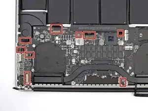
    • Überprüfe bei der Neuinstallation des Logic Boards die Kabel an den gekennzeichneten Stellen, um sicherzustellen, dass sie nicht unter das Logic Board gesteckt werden.

    • Im Uhrzeigersinn von oben: Tastatur, Trackpad, Akku, rechter Lautsprecher, Hintergrundbeleuchtung der Tastatur, Display, Mikrofon, Kopfhörerbuchse, linker Lautsprecher.

    In bullet #1 I lifted logic board from left side (nearest battery), tilted toward right side (port side) and pulled to to the left a bit to get ports out of chassis cutouts.

    Then I followed bullet #2.

    Kitipong Mork -

    Going revese order, remember about mic connector and backlit connector. Those nasty small tails are easy to omit. Then you will have to repeat disassembly to get them from under mainboard.

    Radoslaw Przybyl -

    Agreed with Radoslaw's comment. It might even be nice to have a list of small cables to watch for during logic board reassembly.

    talarohk -

    @radioerewan @talarohk - I think that's a good idea. I went ahead and added a photo showing all the cable locations to check—hopefully it will save someone some trouble! Thanks for your comments.

    Jeff Suovanen -

    This was the single most important pic of the reassembly.

    Mike Jeffries -

    Yes heed everyone’s warning. I had to remove the entire logic board TWICE because i forgot to pull out the antennae and the backlit keyboard plug.

    Jer -

    Yes, be very careful before screwing things down. I also forgot the backlight and the display cables. Had the cover for the display cable out, but not the actual cable. I was able to use tweezers to fish the cables out after removing the screws but without removing the whole board.

    E Carlton Hays Jr -

    My logic board was stuck under the battery PCB, on the top right side of the battery PCB, when viewed like in the first picture.

    I suggest removing the two screws from step 35 holding the PCB down for a little more wiggle room before attempting to remove the logic board.

    Tom -

    I had to go back cause I couldn’t figure out where the logic board connector into (under the board). Funny enough i assembled it and it worked though the night and didn’t come on again. Had to go through the whole process b4 i figured it out. Definitely a good idea to at least breeze through all the images

    Yemi Dalley -

    In link MacBook Pro 15" Retina Display Mitte 2015 Logic Board austauschen step 34 the second picture exit the procedure install ZIP

    raul -

    reassembly: so far the hardest step. After getting all the connectors above board, I still couldn’t quite line up the screw holes. It finally turned out that the board was being prevented from being in its full leftward position because the edge of a flange at the top of the USB port was directly positioned against the edge of a flange on the case. I used my thumbnail to press down on the port’s flange so that it slid under the case flange, allowing the board to shift left another half-millimeter and make everything finally line up.

    Chapman Harrison -

    I Just removed the whole power connector with the main board, seemed a little easier. But that’s just me. Good manual thou.

    Timothy de Wal -

    Had a lot of trouble getting the power cable out. Would definitly recomend this.

    Calvin Truong -

    100% take the power connector out. This guide is amazing but that is something I would change in it. Also I would do step 35 before attempting to remove the logic board. Unsure if there are other implications of this approach.

    kevinhayes656 -

    Am I completely stupid? ...! When I wanted to remove the mainboard, it was still connected to a plug. I searched, but found no indication about this plug. So I had to try to figure out how this plug works. I started trying, which finally tore the console off the board: -o ...: .- ( It is a small plug to the right of the power supply - Pic. #3 top right!!. Comes below the battery. Note, this must be pushed backwards, but may have a lock. What can I do now? If someone has a tip that I do not have to change my motherboard, I am very, very grateful!

    privat -

    I had the same issue where that cable was still connected. I noticed that it was the same type as another one where it needed to be lifted vertically so I did that using the tweesers.

    Jonathan McCaffrey -

    Same problem here, so concerned I might break it I've been working on it for more than an hour! Frustrating to be stuck this late in the process. Anyone know how we missed it in the guide and what it's called?

    Pamela Wilson -

    Definitely unscrew and remove the two screws that hold the MagSafe 2 connector then remove the connector with the board.

    The connector that’s not mentioned in the dissasembly manual is the right hand loudspeaker connector. It pulls up, just the same way as the left hand loudspeaker connector does. No locking tab.

    Other than that it’s a brilliant dissasembly instruction manual, well done.

    I took the logic board out, re-soldered U8900 (well known issue with these boards) and put it back together following the manual in reveres. All works fine now.

    One thing that I did which helped. I printed the manual off, then stuck the screws in every case to the page next to where each screw was described using cellotape. So every screw went back exactly where it came from.

    Steve Hills -

    It is mentioned in step 23, but I agree it was not very clear (I also realised in this step).

    Francisco Daza -

    For me, this step was the most hard part when reassemble. Because it is easy to forget or hard to reconnect MagSafe 2 connector properly. I had to give in to professionals just to find out i couldn’t plug this MagSafe 2 connector properly. because of it’s limited angle and i only have 2 hands to do the job while board is lifted.

    kmg125 -

    Instead of disconnecting the magsafe socket, I unscrewed the two screws holding it to the case. Then, when the logic board is removed, the connector will slide out with the logic board. Also useful to if theres a bunch of magnetic junk stuck to the adapter as it becomes easy to clean.

    max -

    Unscrewing the 2 magsafe screws should be put as a step in the manual. I had a hard time disconnecting the cable and a hard time trying to connect it back when reassembling because there is not enough room to do it and i couldn’t figure out that there is a small clip that holds the connector back in place safely. I had to repeat the role proccess of assemble/disassemble twice in order to fix the magsafe not charging issue. I thought i had lost the connector or damaged the board.

    Jean masaoka -

    Agreed. I found it necessary to unscrew the magsafe power socket from the main board during disassembly to help unplug the ribbon cable from the main board, then screw in the magsafe power socket before the main board during reassembly. The magsafe power socket plug is too short to try and reattach when the magsafe power socket remain attached to the chasis.

    Tim Telcik -

    unscrewing the mag safe as max suggests is a great suggestion. Easier and you can clean the connector.

    klloyd -

    It is not necessary to remove the logic board for this. I did this process without removing the logic board and the 30 steps required to disconnect, remove and reconnect it. It was much easier. Not sure why iFixit insists on removing the logic board: its presence does not block removal of the battery.

    Ben Doherty -

    Why do you need to remove the entire logic board??? Seems like if you detach the appropriate cables, remove the speakers, that that should be enough. Removing the entire board doesn’t seem necessary - what am I missing?

    Sandwah -

    Same question here. What’s the reason behind removing entire logic board?

    Art Skupienski -

    From what i gather, logic board removal facilitates de-adhering the ex-battery units, as the solvent can damage the speakers.

    AKin Adams -

  12. mT3pqV1EMgN3H5cm
    • Entferne die Logic Board Einheit vom MacBook Pro.

Abschluss

Arbeite die Schritte in umgekehrter Reihenfolge ab, um dein Gerät wieder zusammenzubauen.
Brett Hartt

Mitglied seit: 13/04/10

125814 Reputation

0 Kommentare