Einleitung

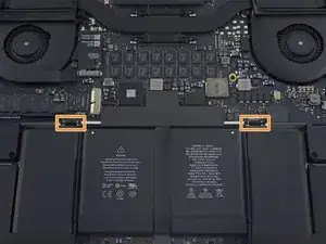
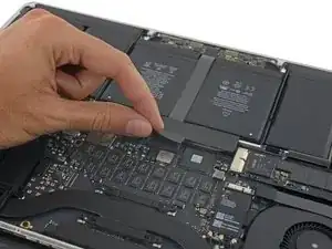
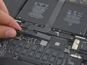
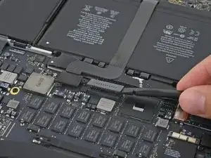
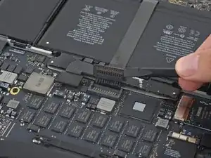
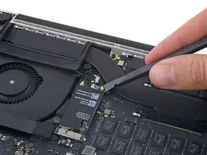
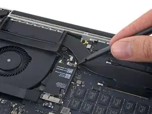
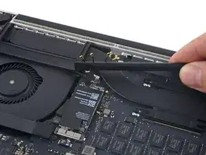
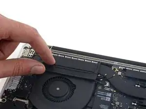
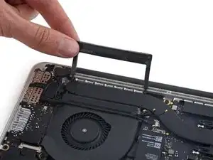
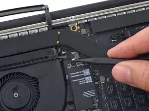
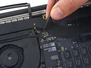
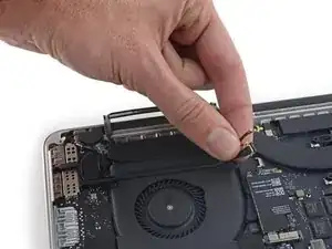
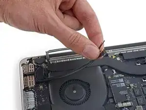
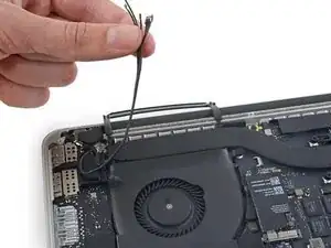
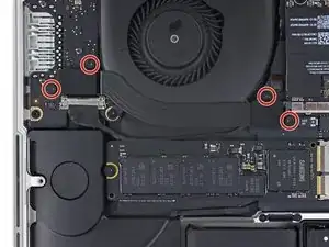
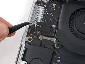
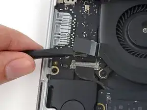
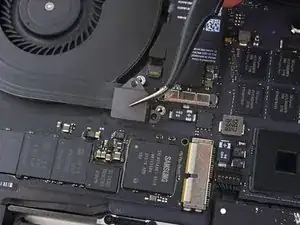
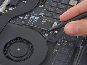
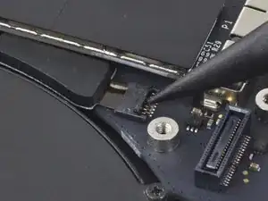
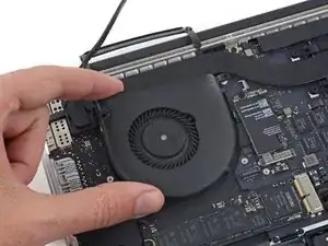
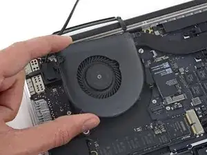
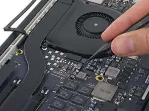
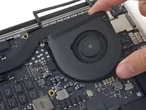
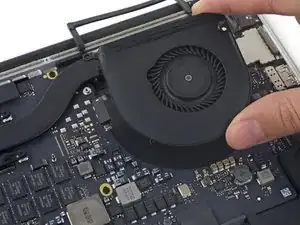
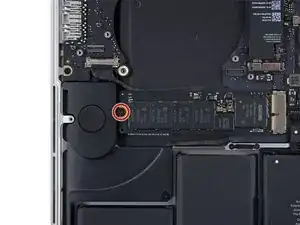
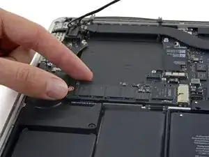
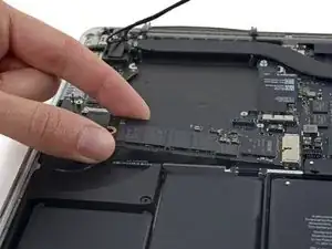
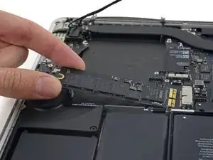
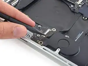
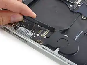
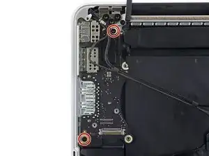
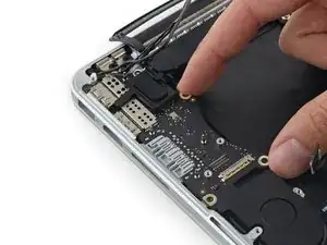
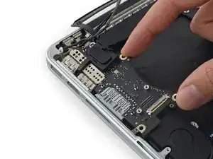
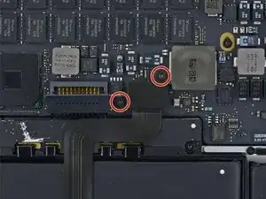
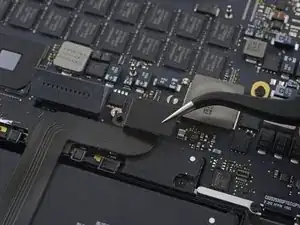
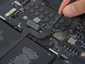
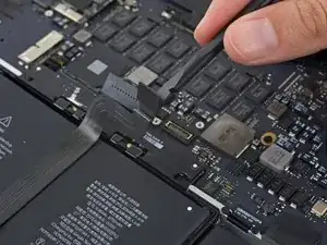
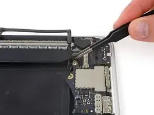
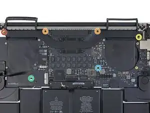
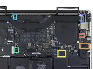
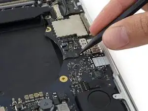
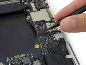
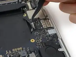
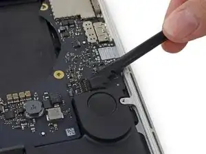
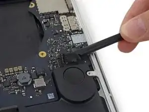
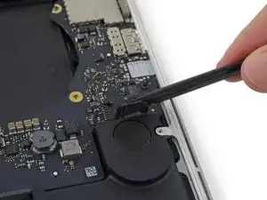
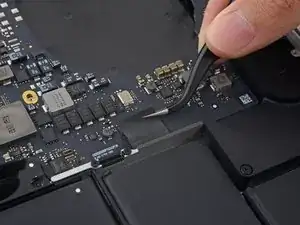
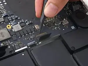
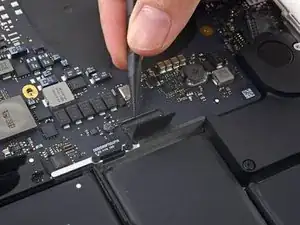
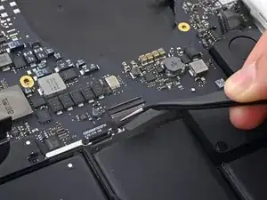
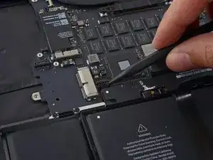
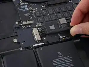
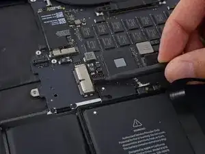
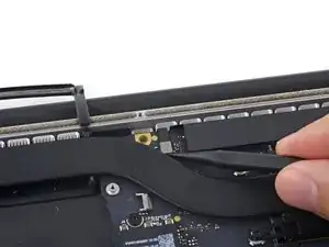
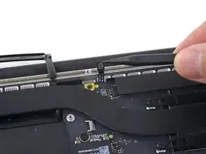
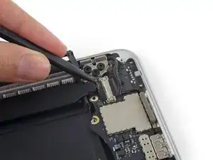
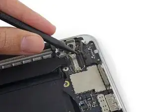
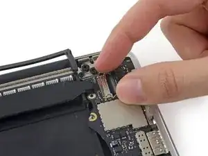
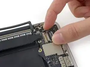
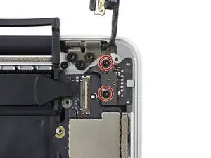
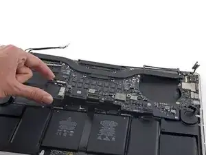
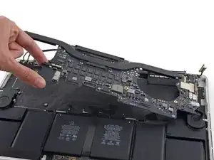
Die beiden Mikrofone deines MacBook befinden sich auf einem Kabel, das unter dem Logic Board versteckt ist. Verwende diese Anleitung, um das Flachbandkabel und die Dual-Mikrofone zu ersetzen.

  1. 4IpJ4MbMOfcwDVDi
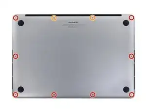
    • Entferne die folgenden P5 Pentalobe Schrauben, mit denen das untere Gehäuseteil am MacBook Pro befestigt ist:

    • Acht 3,1 mm

    • Zwei 2,3 mm

    The number of screws listed here is wrong on my model. I had four of the smaller size.

    anonymous 1286 -

    Just to add to my comment above (I can't edit it because it's anonymous), my MacBook Pro is a mid-2015 15in model 2.8GHz (A1398; EMC2881). For the bottom case it uses six 3.1mm screws, and four 2.3mm screws at the clutch/hinge side of the MacBook Pro. I tried using a 3.1mm screw at the clutch/hinge end, as described in the main article, and they don't fit. It has to be four 2.3mm screws.

    anonymous 1286 -

    The instructions below have you basically taking ALL of the guts out of case. I’ve been doing my own apple repairs since before ifixit was a thing and this one is a handful. My battery was swelling and I wanted to remove it before it burst or bent the case so I took it out without having a replacement and it occurs to me that aside from using the solvent (liquid) to remove the adhesive, you could probably do this only taking the trackpad ribbon out. I have mine reassembled now and will research the best battery to buy but I think installation will take about 5 minutes. See if you can slip a plastic gift card under the battery and wag/saw the adhesive out without the solvent before you go through all of this. It might work. Note, don’t bend or put too much stress on the battery and certainly don’t puncture it…

    br1ansk -

    Battery Recall for 15-inch MacBook Pro Retina mid-2015. Check Apple’s site for recalls, and put in your serial number. They replaced my swelling battery for free, regardless of warranty.

    Steve -

    As we are only replacing the battery, you can safely skip steps 6-26 and 28-48, no need to disassemble the computer to pull out the battery. Use nail polisher remover I was able to pull a super bloated battery out, without disassembling my MacBook.

    John Sikking -

    I qualified for the recall. These bloated batteries are dangerous! DO NOT, UNDER ANY CIRCUMSTANCES, PUNCTURE THE BATTERIES!

    Thanks for the heads-up on the recall.

    Datajockeys -

    I’m having a problem trying to get the screws off. I have a set of pentalobe screwdriver set. I found one screwdriver that fits perfectly on one set of screws, but I am unable to unscrew it. I tried using some force pushing the screwdriver into the screw, but nothing happens. Any suggestions?

    henry_k_wong -

    All the screws on mine are the same length for some reason.

    ccfman2004 -

    I would recommend the first step is: Run the battery down to ZERO before doing any next step. This reduces risk to you, people nearby, to the MBP and greatly reduces the risk of fire. Step 2 should be: Double-check that the battery is at zero.

    I like others listed below and on YouTube, disagree with these full tear down 70+ steps being the only focus. I get that I have to be careful not to get the acetone solvent near the speakers. I skipped 25+ steps by: tilting the MBP away from the speakers and using very little acetone solvent. More pressure with the plastic cards and only a few drops of solvent. While giving the full set of instructions is fine it should be very clear that you can (at the user’s own risk) do this.

    Kenneth Schleede -

    As above—I consider full disassembly to be far riskier to fragile cables and connectors than the risk for solvent spillage. I did steps 1-5 and 46-74. No issues. I HIGHLY recommend the iFixit magnetic Project Mat. It’s a white marker board surface gridded into squares and invaluable for labeling part sizes/steps in disassembly.

    philtrit -

    As above too. I benefitted from the advice. From step 51 onwards, I found a easier way using tip from China battery seller. Use a 2” width plastic scraper/plastic paint scraper to poke under the battery. Use moderate strength to poke and avoid rough handling of the battery so as not to puncture it. There is no need to pry the battery to avoid stressing it, just use a firm poking action under the battery and the double sided tape adhesive will yield. After 5 min of such poking, the entire battery pack can be removed without the hassle of pouring the adhesive remover from step 51 onwards. Get a scraper with a stronger handle so that it is more comfortable to poke.

    https://www.aliexpress.com/item/32889670...

    Emma Pn -

    Heads up as you go…we (husband/wife team) had a notebook that when screws/covers were removed, we marked the step # and actually taped the screws into the notebook noted by the step number. This was very helpful on reassembly and we knew we would be using the exact screw into the original screw hole.

    Ann Brainard -

    After replacing the batteries myself, I wouldn’t even consider doing it again. Not that it’s difficult to do—that’s not the issue. The issue is aftermarket batteries. I’ve been using notebooks for well over 30 years, and never had satisfaction with aftermarket batteries.

    Modern lithium batteries are an amazing technological feat, but a dangerous one. So even putting aside that I’ve never found any aftermarket batteries with quality anywhere near original, I learned “cheap” aftermarket lithium batteries are downright dangerous.

    After doing research into what’s involved with manufacturing lithium batteries, I know there are so many corners to cut, you’ll end up with junk regardless of what you pay.

    A week after replacing my batteries with those from iFixit, they showed clear signs of failure. Thank goodness iFixit refunded my money.

    After having Apple replace my batteries, everything is back to like-new. For my $199, I got not only excellent batteries, but a new keyboard and trackpad as well. That’s it’s done!!!

    AnnoniMoose -

    I found an Apple Support link that said MBP battery replacement was $199, but the 2 Apple Stores near my house would not provide any appointments. Instead, I scheduled an appointment with and “Apple Authorized Service Provider” & that repair center quoted about $750 to replace the battery.

    I refused, went home, & opened a chat with Apple Support.

    After a lengthy & painful chat session where the Apple tech didn’t want to provide a battery replacement quote (he feared other issues with the MBPr), he finally gave me an Apple price of just under $650 to replace the battery.

    Did you go into an Apple store, or mail it in? I’m struggling to reconcile a price of $199 to get a battery + keyboard + trackpad against what I was just quoted 2 weeks ago. The new track pad & keyboard might have been due to repair tech error. i.e. they trashed those repairing your batter & had to toss them in.

    Bartt.Shelton@gmail.com -

    I took mine in after being quoted for a $199 replacement of battery and keyboard, only to have the repair refused as they found a "water sensor" triggered and now I'm left with my AUD$5,000 laptop with messed up keys. Shame on me for not getting this repaired during COVID while under warranty. This is the first time I've truly been disappointed in Apple, but suppose it was bound to happen someday. I was quoted US$ 1479 to replace the battery and keyboard and the sensor (likely the logic board is replaced as well) if I were to send it in to the US repair center. Any chance these sensors can be triggered by humidity?

    C0RT -

    I 1000% recommend watching this video and performing the battery replacement without all these steps from this guide and without using the acetone solvent. https://www.youtube.com/watch?v=ImonCWcc... (15" inch Retina MacBook Pro A1398 Mid 2015 Disassembly Battery Replacement Repair)

    The video is narrated well and the guy goes slow and zooms in where appropriate. Instead of removing all components, he simply removes the track pad cable, battery cable, and unscrews two of the speaker screws on each side. From there, you can lift up the speaker arms where the video guy uses a thin pry tool to push through the sticky tape. No solvent is needed except for residual sticky stuff leftover.

    Instead of the thin pry tool, I just used the plastic cards that came with this ifixit kit. It takes a little force and wiggle/jiggle so take your time using the corner of the card to start.

    This method makes a difficult 2-3hr job into a much easier 1hr job.

    Spencer -

    +1 for this approach! I watched the video that Spencer mentioned. It took me a little over an hour, and it was stress-free. https://youtu.be/ImonCWcc1xk

    Chris Wicklas -

    Another +1 - I followed the video pretty exactly (after having already gone through steps 1-5 here). I'm not sure it's necessary to clean off the adhesive residue as thoroughly as he demonstrates in the video, but the instructions were clear and the end results were good - trackpad still working fine and new battery already charged to 50%.

    Jeff Zinn -

    Glad I read these comments before plunging into the iFixit instructions.

    +1 for skipping the iFixit instructions and using the youtube video linked by Spencer.
    I followed the instructions and had my battery replacement done succesfully.
    Instead of the metal spatula like thing he used - I used the plastic ifixit credit card things that came with my battery kit.
    It took about 15 minutes of wiggling under the battery to free it from the adhesive but it wasn't too bad.
    I did remove the residual adhesive as he indicated with isopropyl alcohol - but after finishing my installation I realized it was completely unnecessary. You can install the new battery over the residual gunk and skip that step.

    picardo -

    Yes! This YouTube tutorial works great and it was really easy to replace the battery. I needed about 75 minutes.

    Perform steps 1-5,

    Then skip to step 41.

    In 41 + 43 do not unscrew the red marked screws.

    In 42 an 45 just lift the speakers, do not remove them.

    Skip 44

    Up from 53, I did not use the glue remover, the plastic cards were enough.

    In step 63 watch out to start from the middle. This prevents you from peeling up the lower „platform“.

    Great job :-)

    weekendiac -

  2. 3ACAiQYIJd3tknWX
    3ACAiQYIJd3tknWX
    DmmoIAmpwTlaYRqB
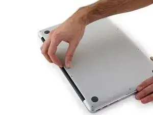
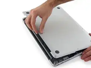
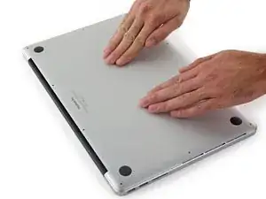
    • Von der Kante, die dem Scharnier am nächsten liegt, hebst du das untere Gehäuseteil vom MacBook Pro weg.

    If you buy the entire kit, make sure you use the opening tool! I cut both of my index fingers trying to slide it off.

    Catherine Nath -

    Additionally, this is an “opportunity” to clean the cooling fans - and any other obvious dust magnets - with a can of compressed air. On the laptop I worked on, the cooling fans had sufficient dust to not “spin” freely - showing signs of “drag”. After blasting each cooling fan with compressed air (including from the exhaust vent side, as hitting the fins alone wasn’t adequate), they both spin freely now. No obvious signs of battery swelling on mine, but lack of adequate airflow could have been a factor with original battery aging/failure.

    Zathras -

    Good opportunity to give a good clean out. Air duster and small clean paint brush on plastic surfaces to clean up essential vents and fans. You can load fan monitor and control software to see what your your system is doing and how it improves with a clean up.

    Robin Razzell -

  3. DT2pWi5FUTaKUDnr
    DT2pWi5FUTaKUDnr
    hXfJjgBexvRBPIZT
    PNXtDrYWjLNP1lus
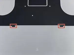
    • Das untere Gehäuse hat zwei Plastikstifte (rot), die in die Plastikklammern im oberen Gehäuse passen (orange).

    • Beim Wiedereinbau die Mitte des unteren Gehäuses vorsichtig nach unten drücken, um das Gehäuse wieder an die beiden Kunststoffklammern anzubringen.

    pretty hard to put it back, so I just remove the clips on the upper case....

    jamiegan835 -

    The trick to putting it back on is to guide your fingers to the same level as the clips, and then when you put the case down move your hand from the left side of the case to the right side of the case; applying pressure when you reach the area where the clips are.

    Aaron Freidus -

    Impossible to put those peds into the upper case clips! It just does not hold there, it fits but just does the ‘click’ sound and goes back. Is it possible to buy those clips as spare part? Thank you for help.

    Lopez Loku -

    Same for me. It just never clips, regardless of the precision and the amount of force I apply.

    Vadym Borodin -

    I also think I stripped the screws holding the clips in place. Does anyone know what screw characteristics should I look for as a replacement?

    Vadym Borodin -

    Bloated battery had already popped my clips.

    jecottrell65 -

  4. f5tSVDDMurTwTaYO
    • Ziehe den Aufkleber ab, der den Akkustecker abdeckt.

    You only need to remove the tape to the edge of the flap. This is enough to be able to pry the battery connector up.

    Aaron Freidus -

    +1 to above comment

    Andrew Saunders -

    Note that the photo is taken from the hinge side - the other way to the photo in step 3

    Toby Thurston -

    I chanced it, didnt disconnect the battery and all is well even after giving the insides a good vacuuming before changing the SSD.

    Dermot O Logical -

    It is just the top layer of tape that you want to lift, you need to seperate it from the bottom layer.

    Kelv -

    You don’t actually need to remove the tape or even peel it off at all. Just pull up the battery connector up with the tape still attached.

    AJ Lorenzo -

    pay attention that the macbook in this picture is presented the “wrong side”: if you accidentally remove the tape covering the trackpad cable and thereby also take the trackpad cable out of the zif-socket, your keyboard and trackpad won’t work anymore. putting the trackpad cable back into the (tiny) socket will fix the issue though.

    sam -

  5. Q4ZkDAWhUSCTyhAV
    Q4ZkDAWhUSCTyhAV
    edxH4LfNEyLYaAlQ
    viOxgCPZueHIeVko
    • Hebe vorsichtig jede Seite des Akkusteckers an, um ihn aus seinem Anschluss auf dem Logic Board herauszuziehen.

    • Biege den Stecker in Richtung Akku zurück, und stelle sicher, dass der Akkustecker nicht versehentlich mit dem Logic Board in Berührung kommt.

    why is this necessary to remove a hard drive?

    Lawtay -

    @lawrencetaylor On any electronics repair, you need to disconnect all sources of power before you start. It’s a basic safety precaution and also removes the risk of accidentally shorting a connection somewhere (which can potentially kill your MacBook).

    Jeff Suovanen -

    I chanced it, didnt disconnect the battery and all is well even after giving the insides a good vacuuming before changing the SSD.

    Dermot O Logical -

    Picture doesn’t match the computer. Hard to tell which connector to disconnect

    James Mitchell -

    Hi James, are you sure you have the correct guide for your machine? Try using our MacBook Identification tool.

    Sam Goldheart -

    Habe den Akkustecker beim putzen abgemacht um keinen Stromschlag zu kriegen, jetzt wieder eingebaut. Nun habe ich folgendes Problem: Akku wird geladen, aber steigt niemals ueber % und manchmal geht er trotz Anschluss an das Stromnetz einfach aus. Hat da jemand eine Idee?

    paul -

    I used the identification tool and can confirm what James is seeing. The picture doesn’t match for this step. There is no piece with visible holes punched in it.

    Joshua McFarland -

    There is an extra piece of plastic on the connector, you might want to peel that off too. It’s not in the pictures.

    Ellie B -

    There is a battery cover with two T5 screws that must be removed before prying on the connector.

    Dennis Newton -

    Hi Dennis,

    Thanks for bringing this up! I’ll work on verifying this and adjust the guide as needed.

    Arthur Shi -

    My battery connector had another layer of plastic on it that I removed first

    Kelv -

    For an A1398, the screws on the adjacent cover were T6, not T5; one of the tips in the battery kit was suitable.

    Zathras -

    I need dis board hw much

    Ebuka Ofodile -

    After separating the battery connector, I took the addd precaution of placing a folded post-it between the connector bank and the socket.

    Matt Fisher -

    You can also use a plastic tool to hold back the battery connector. My connector was under the plastic tab and had no screws. You may need to check the build version as there are a number of A1398 versions.

    Robin Razzell -

    When you install the new battery, it may look like the holes in the connector need to be slid on to the connector toward the rear of the mac. I tried bending the cable to make it work. This could damage the cables. You really need only push directly downward on the connector, as you pulled up on it to remove it initially. It will pop into place with a little pressure, just make sure it's lined up properly.

    Jeffrey Andrews -

    I had to use quite a lot of pressure to make the connector on my new battery pop all the way down. I thought it was down already when it was only half way, as I was afraid to use too much force. Maybe it varies between different battery brands, but just make sure that the connector should go all the way down and not have a gap between the two parts.

    Magnus W -

    " …ensuring that the battery connector doesn't accidentally make contact with the logic board."

    You appear to assume that everyone knows which item is the logic board. I can attest that not everyone does. Clarity here would be helpful.

    Mark -

    If you don't know what the/a logic board is, you probably shouldn't be opening devices.

    Art Hackett -

  6. XyMW1nT1tlFrOs5x
    XyMW1nT1tlFrOs5x
    JaEsQBd5TXP2Xx6M
    tVolyWDEqkKRQ13W
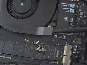
    • Nutze einen Spudger um die drei AirPort-Antennenkabelstecker nach oben aus ihren Buchsen auf dem AirPort Board zu hebeln und biege sie nach oben und aus dem Weg.

    • Die Steckverbinder sind ""sehr"" fragil. Achte darauf, den Hebel nur am Stecker und nicht am Kabel oder an der Buchse anzusetzen.

    • Um die Stecker wieder zu verbinden, positioniere sie vorsichtig genau über der Buchse und drücke sie sanft mit dem flachen Ende des Spudgers wieder fest.

    I seriously hate this step - it is pretty much the only difficult part of the job. Reconnecting these microscopic stinkin connectors is a monumental PITA…

    T Rowe -

    Guys, be very carefull with these 3 cables.. If you are not going to replace the whole display, just be careful as much as possible.

    Adi -

    When reconnecting these tiny wires, use one hand to guide and align the connector by holding the wire and the other hand to press them down with a flat end of a spudger. Spent 10 minutes figuring it out and connecting the first one, then only a few seconds on both of the remaining connectors :)

    If you try to do this with one hand, it’s extremely easy to move them out of the alignment while pressing them down.

    Aivar Kavshevich -

    I think there is a better way - where you disconnect the wifi card using the black screw in middle of wire 2 and 3 first and then untie these connectors. I pryed away the connectors but the sockets on the card were all damaged during the process. Ended up having to get a replacement card before reassembly could be completed. So again there are 2 components - connectors which are being pryed away and really fine and delicate socket. Very easy to damage them. Better to take the card off and delicately peel these connectors off. I would not recommend using these pry sticks mentioned here for that.

    Abhishek Kathuria -

    ATTENTION ! Cette étape est grandement sous-estimée, aucune mention de la délicatesse de l’opération contrairement à d’autres étapes bien plus facile… De plus, il semble possible de sauter cette étape en déconnectant seulement la carte comme expliquer sur la version anglophone du guide !!! J’ai endommagé le connecteur le plus proche du ventilateur, pour rien… Heureusement, tout semble fonctionner correctement…

    Antochny -

    AirPort/Camera Cables? not AirPort/Bluetooth Cables?

    Marco Cappelli -

    Je confirme qu’il est plus simple de déconnecter la carte (enlever la vis, et tirer délicatement sur la carte) que d’enlever les trois cables / I confirm that it’s a lot easier to disconnect the Airport card (just remove the screw and pull gently) than removing those 3 wires.

    Maen J -

    Agreed with Abhishek - removing the wifi card first makes this much easier.

    Tammer Saleh -

    How do you know which is which when reassembling?

    Bryan Province -

    I highly suggest against disconnecting these wires. It's very likely that you will damage either sockets or wires. Do as others recommend, just remove the network card. Prying tool is not good for this step. I broke 1 out of 3 sockets. I wish I read all the comments before operating. Now I gotta get another card :(

    Adomas Aleknavičius -

    what size driver does this require? My pentalobe doesnt seem to be the right size.

    jack32878 -

    As many have mentioned, don’t disconnect the wires is reallly a pain in the a… to connect them, it wont be easy and will take a lot of patience….. Better disconnect the card and carefully leave the wires connected.

    ilukewitschalejandro -

    Just finished replacing both speakers using this guide. VERY good. I did not remove the individual wires - just removed the card with wires attached. Seemed to be the safer, easier way to go.

    Dwight Vaughn -

    How? can you explain the procedure?

    Cosimo Soderi -

    I’m attempting taking the card out but leaving the wires attached as mentioned. A Torx T5 worked for me on that screw. I then very slightly lifted up the end of the card where the wires are attached and pulled it straight out of the slot on the opposite side.

    Sean Gabel -

    Just finished replacing my display LVDS Cable with this guide and another one; awesome. I as well just removed the card and left the wires attached. Much easier.

    Alex DeLeon -

    This is one of those skills that you get experience right after you need it.

    I learned these connectors doing RF work. They require a deft touch. Put slight downward pressure while you work to align the pair. Once you get the hang of it, you will know when they are aligned, and they will go back together with a light push and make a slight snap.

    If they don’t immediately pop together with a light push, they’re not aligned quite right. Don’t force them, they have a very limited number of make/break cycles.

    The cables should retain their bent shape well enough to show where each goes. One it too short to go too far off, and one is too long to fit to the nearest connection.

    prreitz -

    I did not bother with the danger of removing cables or cards or logic board. I spent 30 mins removing my battery carefully, using string and CT1 multisolve which isn’t dangerous to plastic.

    i slid my string under the battery and see-saw underneath and sprayed Ct1 Multisolve underneath. I’ve now done both my macbooks. Didn’t destroy any cables or risk it. I put a few paper sheets over my logic board to cover any spray back. Simple see-saw and a palstic card, the blue spludger and the black long spluger.

    T Master. -

    Yes, I did the full board disassembly on my 2012 macbook last year and once I finished I kind of wondered why I didn’t just work on removing the battery. Is there any real obstacle to doing so here? Can I just spend an hour or so carefully removing the battery? What’s the risk of doing that? again, is there any actual obstacle to removing the battery without pulling out the whole board assembly?

    Brian Lamb -

    You can go straight for the battery if you’re confident enough to improvise a little. Removing the board makes sense if you’re trying to protect the speakers from getting chewed up by the solvent. Otherwise, it’s faster and easier to leave the board in place.

    Jeff Suovanen -

    Agreed. Just replaced the battery on my 15” MacBook Pro 2015 and I skipped all instruction between step 6 and 46. I just unplugged the battery and removed the trackpad connection. Used some dental floss to cut through the adhesives and a card to help with carefully prying the batteries up. After the battery was removed I used some isopropanol to clean up from the old glue. Installed new battery, attached the trackpad connection ribbon and connected battery. All in all it took me less than one hour. I would not recommend removing the whole logic board just to replace the battery.

    Mackie72 -

    I’m one of those unfortunate ones that simply followed the iFixit instructions before reading the comments. On successfully reconnecting 2 of the cables and (miserably) failing with the 3rd, I realized the relevance of the comments. I decided to take a gamble and leave the 3rd connector unconnected and fired up my MacBook … strangely enough, everything works fine i.e from the comments, WiFi, Bluetooth, Camera (et al) should be affected but they are all still fully operational (maybe they’ll die with time - I hope not). I don’t like the thought of an unattached cable lying around in my Mac hence I agree with those advocating for alternatives to this step (unhinging the WiFi card as opposed to prying these cables).

    Otim Samuel -

    Diese drei winzigen Stecker wieder aufzusetzen war tatsächlich die größte Herausforderung der ganzen Reparatur! Wichtig ist dabei darauf zu achten, diese waagerecht und passgenau aufzusetzen. Ich habe dazu die Lupe meiner Lötvorrichtung genutzt und zum aufdrücken die flache Seite des Spudgers.

    Werner Hampl -

    These antenna connectors are the worst to reconnect. Depending on the model and what repair you are doing, you may not be able to avoid disconnecting them.

    ccfman2004 -

    We took the advice of leaving the wires attached to the card, and unhinging the wifi the card cable. Worked great for us.

    Ann Brainard -

    Ditto on just removing the card and leaving the antenna connected. Worked fabulously.

    Matt Fisher -

    If you do need to get the cables back on the the card, I have found good results using the tip of a T5 driver to gently push them down (of course while aligning carefully with other finger). It gives a firm, flat & precise surface to press with + we know you have a T5 around!

    Tech Medic -

    Why do these wires/sockets need to be removed at all? They seem like they are pretty faraway from the battery.

    John Sikking -

    As we are only replacing the battery, you can safely skip steps 6-26 and 28-48, no need to disassemble the computer to pull out the battery. Use nail polisher remover I was able to pull a super bloated battery out, without disassembling my MacBook.

    John Sikking -

    Can I replace it with early 2015 monitor? Couldn’t find a cheap mid 2015 one but I found a reasonably priced early 2015 one and I would like to have it ?

    Mohammed -

    If you’re just replacing the battery, after step 5 you can skip everything else except 26-27, 34, and 50, and then continue from step 56 onwards. Instead of needing an adhesive removal, I just used a credit card to separate the battery cells from the casing they’re glued to.

    Petr Bela -

    After step 5, I would skip 26-27, 34 and just to 46-50. You need to remove the cable from the battery, so even if you do 26-27 and 34, you'll need to do 46-50.

    I use the solvent to remove the left over glue after the battery has been removed, but have been able to separate the battery by just sliding a card between the battery and case.

    maccentric -

    I'm here to tell you that it is possible to remove and reassemble these wires, despite all the above comments making it seem almost impossible. I was planning to remove the entire card instead, but accidentally popped one of the wires when trying to get the card out. So then I just figured I might as well follow the instructions. Popping them was easy, getting them back on was a bit more tricky. Use a fine tip plier to hold the wire and place the plug in place, then press down (quite firmly!) with a spudge or something flat (I would advise against using a metal tool such as the torx driver, in case you slip and hit something). As long as the plug is directly above the connector and aligned properly, you won't break it. Use a good light source and a magnifying glass if needed. I brought my adjustable desk up to eye level so I could come really close and see what I was doing.

    Magnus W -

    Before removing the wires, I recommend marking each with for example some tape so that you know in which socket to place them when reconnecting them later.

    Lennart Philipp -

    I got to this step and read a few more and was like oh shoot. I cannot be without my laptop if i mess something up and break a cable. The advice was right. I skipped all the extra removal pieces and just removed the battery. I did step 1-5. Then did step 26 and 27. Then steps 33 and 34. The finished with steps 46-51. I didn't have the blocks so i bypassed putting the laptop on a slant. so after step 51 i skipped to 56 and just started prying off the battery with a credit card and other ifix it tools. I do think the adhesive remover would be very helpful. I also wore goggles cause i caused a spark when i accident poked one of the batteries. Laptop is fine but it is very time consuming and difficult. I recommend getting the kit with the battery. Its only 10 bucks more and i think it would have saved me heaps of time!!!

    kyle hansen -

  7. pM45BTX5cqlTG4pR
    pM45BTX5cqlTG4pR
    UN5fKSKYtOq5YFMk
    • Ziehe die rechte Gummiabdeckung vom Lüfter ab und klappe sie aus dem Weg.

  8. WLOuTNVVKgbYETtf
    WLOuTNVVKgbYETtf
    t4PXHjFut5bHTsMj
    • Verwende die Spitze eines Spudgers, um den Stecker des Kamerakabels aus seinem Anschluss auf dem Logic Board zu schieben.

    • Achte darauf, dass du den Stecker parallel zum Logic Board schiebst. Am besten schiebst du ihn zuerst auf der einen Seite und dann auf der anderen Seite aus dem Anschluss heraus.

    This connector is very fragile, the left edge of mine cracked off and ended up in the socket. And during figuring that out the cable or the socket appears to have got damaged because “no camera detected”.

    malhal -

    Yeah, same here.. Not sure what to do now

    Roman Kroupoderov -

    Have you found a solution to this problem ? I have the same issue

    Tim Rault -

    All connectors are incredibly fragile. I damaged the fan connector locking latch just by trying to lock it back in place. Fortunately the cable, by the way it inserts, it’s being pushed in rather than pulled on, however, I do have concerns with it not making a proper connection. Malcolm, I am wondering how you fixed your damaged connector?

    Robert Habib -

    The connector slides into the socket so using the flat end of the Splunger under the cable and gently lifting draws the connector apart.

    Dennis Newton -

    Don’t use the flat edge of the spudger. Instead, use the pointed end to gently slide off by the dog ears of the plug. If you look closely you’ll see a notch on each side.

    John Xeno -

    supplied tool does not have a fine enough point here - won’t move at all

    Paul Forgey -

    I used the fine point and also used the tweezers under the plug to relieve some pressure. I was very, very careful and made small moves. I seemed to get it out with no damage.

    Al Moulder -

  9. KCDcDX5CcvygyyRK
    KCDcDX5CcvygyyRK
    Oh24SLQTbWh4VKZB
    YfKuTlxVSlGYyZfk
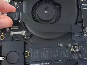
    • Ziehe die AirPort-/Kamera-Kabel mit den Fingern nach oben vom Lüfter ab.

    • Die Kabel sind mit dem Lüfter verklebt, ziehe also vorsichtig, um Beschädigungen zu vermeiden.

    • Fädle die Kabel vorsichtig aus ihrer Kunststoffführung.

    • Bei der Wiedermontage sollte noch genügend Kleber auf diesen Kabeln vorhanden sein, um sie wieder an den Lüfter kleben zu können.

    Leave them attached. Remove the single screw holding the board in place and gently wiggle the airport card out (see Airport card removal instructions). Fold the card up and towards the rear of the computer. Now follow the instructions for the camera cable removal. Lift the airport card with the three leads attached and the camera cable up and fold the, to the outside of the case.

    George R. O'Connor -

    This video shows how to do it safely: https://www.youtube.com/watch?v=AabLlHT5...

    Undo the 3 cables gently. remove the airport card. gently pry away the cables fro the fan plastic. then the camera cable will slide out easily.

    T Master. -

    I was afraid to just pull on any cables adhered, so I used a spudger edge to very gently “scrape” them up instead.

    Matt Fisher -

    It was much easier following the instructions on the YouTube video, thanks! Looks like the process starts around 4:11.

    Darnell Remy -

    why are we completely tearing the computer, just to replace the battery?

    surely tearing it down could do more damage than being careful removing the bloated battery

    Russell G Stewart -

  10. VZOsrdBRm4RIeIcg
    • Entferne die vier 2,2 mm T5 Torx Schrauben, welche die Steckerabdeckungen des I/O Board Kabels befestigen.

    why is this needed for upper assembly replacement?

    Andrew Chu -

    My cable connector covers are not screwed down. Mid 2015 15” MBP. That’s the computer in the title of this article so idk.

    Andrew Sauk -

    I’m having trouble breaking the 2.2 mm screws loose and I don’t want to strip the head. I’m using the T5 screwdriver. Does anyone know any tricks or suggestions?

    Madeline Young -

    Ok, so the correct size Torx is the T4, not T5

    Madeline Young -

    Is this really necessary just to replace the LEFT speaker?

    Troy Havard -

  11. FnEfIq5cpNfjgTmA
    FnEfIq5cpNfjgTmA
    CMDPoK5Auva1bGbE
    • Entferne die Steckerabdeckung links.

    • Verwende das flache Ende eines Spudgers, um das linke Ende des I/O-Board-Kabels von der Buchse auf dem Logic Board nach oben zu ziehen.

  12. pfTC14BhpQRGgcEh
    pfTC14BhpQRGgcEh
    cQslcXDZD61lZAPp
    • Entferne die rechte Steckerabdeckung.

    • Verwende das flache Ende eines Spudgers, um das rechte Ende des I/O Board Kabels von seinem Anschluss auf dem Logic Board zu hebeln.

    When re-assembling, the right connector cover is the smaller of the two.

    richardgraham_2000 -

  13. ZSlYr1nvCIcUkshb
    • Ziehe das I/O-Board-Kabel von der Klebeverbindung zum Lüfter ab.

    • Entferne das Kabel.

    Cable need not be removed.

    mayer -

    Totally agree.

    John Gerdes -

  14. oLQnDNB5OfZZybDN
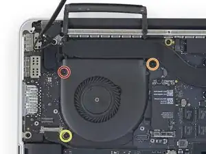
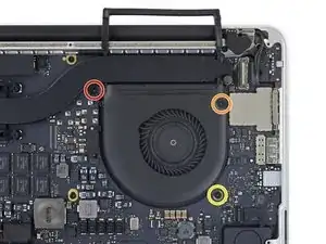
    • Entferne die folgenden drei Torx T5 Schrauben, welche den rechten Lüfter am Logic Board befestigen:

    • Eine 5,0 mm Schraube mit einem 2,0 mm langen Bund

    • Eine 4,0 mm Schraube mit breitem Kopf

    • Eine 4,4 mm Schraube

    The orange colour coded one is more mushroom shaped than the other screws (their size is not easy to otherwise tell apart)

    Howard Graff -

  15. isUs2lgiHxcr6BOK
    isUs2lgiHxcr6BOK
    ctGJX2hRspAmNpjQ
    iJ1sABCRC3UWqDbT
    • Verwende die Spitze eines Spudgers, um die Halteklappe am ZIF-Anschluss des rechten Lüfter-Flachbandkabels nach oben zu klappen.

    • Vergewissere dich, dass du den Hebel an der Halteklappe ansetzt und nicht am Anschluss selbst.

    A note about these ZIF sockets - the retaining flap is just held in place by the small amount of friction, and on reassembly they can separate. I learned to push them down with my finger when possible, or else with a flat end, carefully walking them down side by side to keep it as even as possible. If the flap separates all is not lost ! It’s quite difficult (I did almost everything in this guide with tweezers under magnifiers) but if you remove the cable first, you can get the plastic “comb” back under the pins and up into it’s original position, then replace the cable and try again.

    Matt Fisher -

    I was gonna comment that I broke the retaining flap off the connector, but per Matt’s comment above I guess it just separated off.

    Anyways while holding the flap part in a pair of needle nose tweezers the tweezers closed and shot the flap off like a bullet somewhere in my living room lol. So be careful if it does separate on you haha.

    Robert Perez -

  16. oWcnXRWQKX21tWSe
    oWcnXRWQKX21tWSe
    2fYeGqpnViXao1Hq
    • Hebe den Lüfter an und schiebe ihn vorsichtig nach hinten, um das Lüfterkabel aus dem Anschluss zu ziehen.

    • Das Lüfterkabel könnte am Logic Board festgeklebt sein. Um zu verhindern, dass es abreißt, musst du es ganz vorsichtig ablösen, während du den Lüfter nach oben hebst.

    • Entferne den Lüfter.

    I recommend pushing the cable connector away with a spudger instead of using the fan to pull it away…there seems to be too much stress put on the cable using the method proposed here.

    Bill Klemme -

    Using a spudger does help alleviate stress on the cable. I also used it to help get the cable up from being adhered to the logic board.

    Joshua McMillan -

    Adding to the other comments, the fan is very light and has no resistance lifting out of the place it sits in.

    I carefully lifted the fan just before there was any tension on the cable.

    With the fan held in my right hand and spudger in my left, I moved the spudger under the fan approaching from the left side.

    This allowed me to easily place the flat end of the spudger under the cable where the thicker plastic sits and gently pry the cable up until the cable broke away from the body.

    I then used the pointed part of the spudger to gently pry the connector part of the cable away from the socket while gently pulling the fan away until the cable was disconnected and the entire fan was free.

    David Carroll -

    Terrible instructions on this one. I thought I was supposed to pull the cable off the bottom of the fan! Not photos showing the final result. Finally the cable on the right came away from the board and out of the socket with the flap lifted up. Please make this clearer or damage to the cable can take place.

    peter -

    Instructions are faulty. After removing fan screws and lifting the retaining flap, lift the fan with one hand while gently pushing the connector with the flat side of a spudge toward the back of the chassis. It should slide off.

    codyking411 -

    I definitely needed to use the spudger to gently lift the cable from the board while holding the fan with one hand. The cable was stuck on the board pretty well. Once I broke the seal it was a simple case of pushing it out of the connector.

    Al Moulder -

  17. yjMmvu6kyDX1hw2b
    yjMmvu6kyDX1hw2b
    KTaG6ajuABS2GQWM
    • Ziehe die linke Gummiabdeckung vom Lüfter ab und klappe sie aus dem Weg.

  18. g6KZqeMB4MT1IYM3
    • Entferne die folgenden drei Schrauben, welche den rechten Lüfter am Logic Board befestigen:

    • Eine 3,6 mm T5 Torx Schraube mit Breitkopf

    • Eine 5,0 mm T5 Torx Schraube mit einem 2,0 mm langen Bund

    • Eine 4,4 mm T5 Torx Schraube

    the yellow one may not go back in during reassembly unless the board is perfect. Stripped mine in the effort - put back together without this screw :(

    Paul Forgey -

    I ran in a similar misalignment so had to bend the top left loop a bit to make it fit.

    Not a big issue, but better to lay it in and check the alignment of all screw holes (and adapt if necessary) before putting the screws in.

    I saw my replacement part had already a bit of paint missing at the top left and bottom right holes, so I assume it is a refurbished or sourced part, so a bit of tweaking may be necessary. BTW, the fan works perfectly, no more annoying clicking noises.

    Maarten S -

    The red-coded one is the most mushroom-shaped screw this time. (biggest, flattest screw head)

    Howard Graff -

  19. KZLoBgOrKrwLJyCp
    KZLoBgOrKrwLJyCp
    QPxUOKySgxlEYDES
    • Verwende die Spitze eines Spudgers, um die Halteklappe am ZIF-Anschluss des linken Lüfter-Flachbandkabels nach oben zu klappen.

    • Vergewissere dich, dass du den Hebel an der Halteklappe ansetzt und nicht am Anschluss selbst.

  20. FQulGdw1K5XYWmxa
    FQulGdw1K5XYWmxa
    U1xQpvnCkUKT1fOP
    • Hebe den Lüfter an und schiebe ihn vorsichtig nach hinten, um das Lüfterkabel aus dem Anschluss zu ziehen.

    • Das Lüfterkabel könnte am Logic Board festgeklebt sein. Um zu verhindern, dass es abreißt, musst du es ganz vorsichtig ablösen, während du den Lüfter nach oben hebst.

    • Entferne den Lüfter.

  21. 2kSO1hoHrblQI4Yb
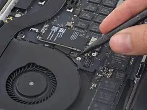
    • Entferne die einzelne 2,9 mm T5 Torx Schraube, mit der die SSD am Logic Board befestigt ist.

  22. QHT5QPPBSCBG4udJ
    QHT5QPPBSCBG4udJ
    CnQOtBVOCmkOYRFd
    OZ4SgJtyNMD2fBQg
    • Hebe das Ende der SSD so weit an, dass es über dem direkt dahinter liegenden Lautsprecher ist.

    • Hebe die SSD nicht zu hoch, da sonst die Kontakte oder die Buchse beschädigt werden könnten.

    • Ziehe die SSD gerade aus ihrer Buchse auf dem Logic Board heraus.

  23. UXB5bRHwcPCjtT2L
    UXB5bRHwcPCjtT2L
    BZcnkhC1Y1ndKLV2
    RqaQxLKZ3aLe1kZu
    • Verwende die Spitze eines Spudgers, um den Verriegelungsmechanismus des I/O-Board-Steckers nach oben zu klappen.

    • Drehe den Spudger um und schiebe das I/O-Kabel mit dem flachen Ende aus dem Stecker heraus.

    • Drücke auf den geöffneten Verriegelungsmechanismus, dann kannst du das I/O-Kabel ganz einfach aus dem Stecker herausziehen. So kannst du auch versehentliche Beschädigungen der Kabel- oder Steckerkontakte vermeiden.

    Oh, you rotated the computer while I wasn’t watching.

    prreitz -

    That's really tight on this connector. I found it slightly easier to reconnect with the expansion board not in place..

    Alan Dike -

    The locking-bail is on the the cable part of the connector.

    Richard Bugg -

  24. oHKr3idYfYFypwik
    • Entferne die beiden 3,1 mm T5 Torxschrauben vom I/O Board.

    Remove the screw holding the heat pipe, it blocks the I/O board from coming out

    Gert Cuykens -

    It's interesting that you had to remove the heat pipe screw. This didn't seem to be in the way for me. The I/O board came out quite easily without any issues.

    But… it could be different for others as it was for you. I just thought I'd share my experience.

    David Carroll -

    Thanks for the tip! I also had to remove that screw to get the board out.

    maccentric -

    The board was not coming out for me until I removed that heat pipe screw. Thanks for the tip!

    Al Moulder -

    Also make sure the I/O cable removed on previous step is out of the way before screwing this down

    Keith Kern -

    Me too. The heat pipe screw overlapped the I/O board slightly, but very securely held it down on mine. Had to be removed.

    Patrick Nance -

  25. ghZ1KUS5BKvKmeQV
    ghZ1KUS5BKvKmeQV
    I5JonCeZEvXNnXlj
    • Hebe die Innenkante des I/O-Boards leicht an und ziehe sie zur Mitte des MacBook, also von der Seite des Gehäuses weg.

    • Entferne das I/O Board.

  26. nXYZxlXybYp2WXHn
    nXYZxlXybYp2WXHn
    CH6BErvRpxNVAaBE
    • Entferne die beiden 2,2 mm T5 Torx Schrauben, welche die Abdeckung des Touchpad-Kabelsteckers am Logic Board befestigen.

    • Entferne die Abdeckung.

    I'm confused why it's necessary to remove the entire logic board to replace the right speaker?

    Don't you just need to remove the I/O board for the right speaker?

    Steve Rieck -

  27. bxDQI1QGgX2ock1U
    bxDQI1QGgX2ock1U
    ugAQSUqdKmkdo5jM
    ASKMc61pMrsXNOhR
    • Verwende das flache Ende eines Spudgers, um den Stecker des Touchpadkabels von seiner Buchse auf dem Logic Board zu trennen.

    • Wenn du das Ende des Spudgers ein bisschen hin- und herdrehst, kannst du den Kabelstecker relativ leicht aus der Buchse hebeln.

    • Achte darauf, dass du den Hebel auch wirklich am Stecker ansetzt und nicht etwa an der Buchse auf dem Logic Board selbst.

  28. OxjrwPwrowQATefd
    • Entferne eine kleine Gummikappe von der Schraube am Ende des Kühlkörpers.

  29. 2BgFh3plOh2lfU2F
    • Entferne die folgenden sechs Schrauben, mit denen die Logic Board Einheit am oberen Gehäuse befestigt ist:

    • Eine 3,8 mm T5 Torx Schraube

    • Zwei 5,7 mm T5 Torx Schrauben

    • Eine 5,6 mm T5 Torx Schraube (diese ist silberfarben und hat einen höheren Kopf als die anderen)

    • Eine 2,6 mm T5 Torx Schraube

    • Eine 3,2 mm T5 Torx Schraube

    • Beim Wiederzusammenbau musst du zunächst alle sechs Schrauben einsetzen, aber noch nicht festziehen. Bewege das Logic Board ein bisschen hin und her, bis alle Schrauben in den Bohrungen zentriert sind und die Anschlüsse mit den Öffnungen an der Seite des oberen Gehäuses ausgerichtet sind. Ziehe danach alle Schrauben fest.

    Top left and right screw (red, yellow) are silver, the other ones black.

    Peter G -

    Screw with blue circle was in a slightly different position on my logic board; the gold plating surrounding it is the giveaway.

    prreitz -

    This step is really best done after all the cables are removed (Step 40).

    maccentric -

    On the other hand, when reassembling, keep the screws until this step 29

    Patrick Nance -

    The red screw above is the same one I had to remove to remove the I/O board back in step 24

    Al Moulder -

  30. bvP3EeBrBxPrx5YK
    • In den folgenden Schritten wird detailliert beschrieben, wie du diese sechs Anschlüsse trennst. Lies dir unbedingt jeden Schritt durch, da diese Anschlüsse verschiedene Bauformen haben und deshalb auch auf unterschiedliche Weise zu trennen sind.

    • Mikrofonkabel

    • Kabel des linken Lüfters

    • Tastaturdatenkabel

    • Kabel des rechten Lüfters

    • Tastaturhintergrundbeleuchtungskabel

    • Displaydatenkabel

    • Überprüfe beim Wiederzusammenbau, ob alle diese Anschlüsse angeschlossen sind und vollständig in ihren Buchsen sitzen.

    Save this step until you get to step 40

    I would wait until after step 39 to remove these screws. Once they are removed, the logic board jiggles around and makes disconnecting the various cables in 31-39 more difficult.

    Daniel Christie -

    Bild/Schritt 30: Bitte beide Wörter "Lüfters” durch “Lautsprechers” ersetzen

    Norbert -

    Agree with Daniel Christie. Wait until step 39.

    Patrick Nance -

  31. OkKAvgxV6J25PkZd
    OkKAvgxV6J25PkZd
    lkDLStTM6AqCKOWI
    gKLGsTErD5APuZiw
    • Klappe mit der Spitze eines Spudgers die Halteklappe an der ZIF-Buchse des Mikrofon-Flachbandkabels nach oben.

    • Ziehe das Mikrofon-Flachbandkabel parallel zum Logic Board aus der Buchse.

    This cable was pretty hard to remove at first. I had to gently wiggle it from side-to-side in the socket before it would let go.

    Jamie Flournoy -

    I had the same issue. This was the hardest cable to remove imo. i was afraid i was going to tear it which as hard as i needed to pull it. I ended up leaving this cable inserted until the logic board was fully unscrewed to give me a bit more wiggle room.

    Joseph Dale -

  32. JKB6EAWruKTlF3vP
    JKB6EAWruKTlF3vP
    rgb5Zf3ARtZPCOQR
    bQ6uPW4nIkXYrwZh
    • Verwende das flache Ende eines Spudgers, um den linken Lautsprecheranschluss aus seiner Buchse auf dem Logic Board herauszuziehen.

    • Achte darauf, dass du den Hebel auch wirklich am Kabelanschluss und nicht etwa an der Buchse auf dem Logic Board ansetzt. Wenn du an der Buchse ansetzt, könnte sie sich vom Logic Board lösen.

    • Falte das Kabel vorsichtig nach oben vom Logic Board weg und aus dem Weg.

    this cable was stuck down, so I had to wiggle the spudger under the cable first to separate the adhesive. Then it came away easily.

    Pete Bagnall -

    Same here, the cable was stuck down pretty. Thanks Pete, your advice helped a lot.

    Al Moulder -

  33. HZpHp2FnRNDY2iYZ
    HZpHp2FnRNDY2iYZ
    QwmCjQI1mPgHGfZM
    • Ziehe das Klebeband ab, das den Anschluss des Tastaturdatenkabels verdeckt.

  34. OyKCVZGB5MsPBycV
    OyKCVZGB5MsPBycV
    Y3KwHS1pHCJKbeds
    26Q2B2AYFPjQvjDJ
    • Mit der Spitze eines Spudgers kannst du jetzt die Halteklappe an der ZIF-Buchse des Tastaturdatenkabels hochklappen.

    • Vergewissere dich, dass du nicht an der Buchse selbst, sondern wirklich an der Halteklappe ansetzt.

    • Ziehe das Tastaturdatenkabel aus seiner ZIF-Buchse heraus. Achte darauf, dass du parallel zum Logic Board ziehst und nicht gerade nach oben.

    The retaining flap broke on me during reassembly. I was careful, but it kind of got stuck. Pay extra attention and if it doesn’t give, don’t force it.

    vincentdrummer -

    Same thing happened to me. Didn’t really put much pressure either.

    meadowsd -

    Same there here.. I ended up using some tape to ensure the cable stayed seated upo nreassembly

    Alan Dike -

    hey its not a kick, take it easy on it. after replacing my battery my keyboard (and not Richards keyboard) and track pad are non responsive, Russell Stewart old neighbour .

    Russell G Stewart -

    The last picture doesn’t show it but my cable had blue plastic material on both top and bottom, which I had not noticed during disassembly. It slid in nicely but now not sure if it is an insulating material of some kind that should have been set aside?

    Bill Klemme -

    I can confirm blue colour of cable tip.

    Mighty Sashiman -

    The retaining flap broke off on us during reassembly also…we (husband/wife team) were very careful, but the center piece just broke out when we applied pressure. the blue material did fit under the cable socket (like a smooth blue ribbon), but without the retaining lock, was unsure it would stay in position. We pulled the tape over it and hoped all would work. Everything seems to be working fine for us.

    Ann Brainard -

    The retaining flap broke on me as well and caused a near panic. I actually managed to fix it by careful inspection under magnifier and some trial and error with tweezers. The retaining flap itself is comb shaped - a solid edge and then combs that come out between the wires., and apparently just held in by the tiniest of detents. After trying unsuccessfully to push it back down between the wires, I surmised that the gaps in the “comb” side for the wires were sealed loop and that the wires it sat on were open ended. So I eventually ended up lining the flap up as if it were closed, and then carefully nudging it up onto the top wires, which was succesful, and then pushing it back into the open position to get the detents in place. Then to close it after reinserting the cable I walked it down bit by bit by pushing forward and *downward* on each side to help it maintain it’s ‘hinging’ effect. I think frankly you’re better off pushing larger ones like these down with your finger instead of a tool.

    Matt Fisher -

  35. NDYJfgEhIaTjnaUN
    NDYJfgEhIaTjnaUN
    liQdmwrTgdeLOVJG
    tnHQNkcsefaqHOC4
    • Verwende das flache Ende eines Spudgers, um den linken Lautsprecheranschluss aus seinem Anschluss auf dem Logic Board herauszuziehen.

    • Achte darauf, dass du den Hebel am Kabelstecker und nicht am Anschluss auf dem Logic Board ansetzt. Wenn du am Anschluss ansetzt, könnte er sich vom Logic Board lösen.

    • Falte das Kabel vorsichtig nach oben vom Logic Board weg und aus dem Weg.

    There's not much space here to work with. I found it helpful to remove the screws holding down the battery board, which allowed it to be lifted out a bit for easier access to this connector.

    maccentric -

    I used the tweezers on this and that was very effective in popping this cable out.

    Al Moulder -

  36. S2sBUZtwQh64VTip
    S2sBUZtwQh64VTip
    RX4xRMjdqlqKTDMj
    • Benutze die Spitze eines Spudgers, um den Anschluss für die Hintergrundbeleuchtung der Tastatur von der Buchse auf dem Logic Board nach oben zu ziehen.

    On reassembly it would be great to have some tips on how to properly locate this connector…it’s kind of fussy.

    Bill Klemme -

    Thanks for calling this out. I took a picture of the socket after disconnecting. I can see why it might have been less obvious on reassembly.

    David Carroll -

    Also on reassembly - when putting in the logic board make sure this connector is not underneath. Once you have the logic board in, double check and if needed you can slightly lift up the logic board (like to take it out) and use the spudger to scoop it out.

    Jason Joyner -

    I found that this was actually really easy to get back on by using my finger instead of a tool, as I could just wiggle it back and forth slightly until I felt it seat. Hopefully using your fingers isn’t verboten - I was strapped in at the time and everything worked out in the end.

    Matt Fisher -

    the picture is mirrored

    Daniel Luescher -

    The picture is not mirrored if you see the heat sink that curves to the up and left it is not mirrored.

    Will Greider -

  37. BuAmdDqEMCpcWyxb
    BuAmdDqEMCpcWyxb
    mD3dQrBeODOJ5wlN
    • Verwende die Spitze eines Spudgers, um den Verschluss des Displaydatenkabels nach oben zu klappen und ihn in Richtung MagSafe 2-Powerport zu drehen.

    +(mit dem schwarzen Klebeband zusammen)

    Verwende die Spitze eines Spudgers, um den Verschluss des Displaydatenkabels nach oben zu klappen (mit dem schwarzen Klebeband zusammen) und ihn in Richtung MagSafe 2-Powerport zu drehen.

    Mihály Plajner -

    My mid-2015 has a flexible plastic tape on the cable lock bar, pulling the tape up with tweezers easily rotated the locking bar.

    prreitz -

  38. VBKUIUvAUB2riq6t
    VBKUIUvAUB2riq6t
    rmIXrN5PAVLVIN5R
    WCcAUuooVfJWHnPy
    • Ziehe das Displaydatenkabel gerade aus der Buchse auf dem Logic Board heraus.

    • Hebe das Datenkabel des Displays nicht nach oben heraus, da dessen Buchse sehr empfindlich ist. Ziehe das Kabel immer parallel zur Stirnseite des Logic Boards.

    • Berühre die Kontakte des Datensteckers oder dessen Buchse nicht mit den Fingern oder mit irgendwelchen Werkzeugen, da es sonst zu Ölverschmutzungen oder Beschädigungen der Stifte kommen kann.

    • Biege das Displaydatenkabel vorsichtig zum Displayscharnier hin, um die Schrauben auf dem MagSafe 2 Board freizulegen.

    The wording of the instruction: “Pull the display data cable STRAIGHT OUT of its socket on the logic board” could lead to errors. It almost happened to me.

    Instead you should word it: “Pull the display data cable parallel to the face of the logic board being careful to keep it straight and NOT LIFT UP on the cable”.

    I realize you mention it later in the warning immediately below, however, by first saying “pull the cable straight out” leads to confusion and could lead the user to attempt to interpret “PULL STRAIGHT OUT” as “PULL UP” unsuccesfully only to later notice, maybe after breaking it, that there was a warning.

    Wording it properly the first time will make the warning unnecessary.

    Robert Habib -

    I had the same thought as I almost proceeded without noticing the red text warning.

    I especially think the second warning about not touching the contacts on the data connectors should be listed before the instructions on removing it.

    David Carroll -

    Agree with Robert. Suggest “SLIDE the display cable to the right, out of its socket…” would be less misleading.

    prreitz -

    I think it bears repeating just how fragile this connector is, particularly on reinsertion. The problem isn’t just technicians touching the connector end; you can damage the pins simply by inserting it slightly out of alignment, or at an angle, because the outermost pins are VERY close to the edge and are very fragile. They have the appearance of being embedded in the connector but they’re actually spring traces just lying on top of it. I managed to bend the southmost pin upwards reinserting it; luckily it flattened out again and worked, but if it had not been possible to do that it’d have been a whole new screen assembly.

    Jerome -

    I’m pretty sure I inadvertently touched the connectors. Would this cause immediate errors or obscure, difficult-to-diagnose problems later in life ? Also strongly suggest using magnification when disconnecting and reconnecting this connector and others to ensure proper alignment. As Jerome said these are some of the most fragile parts of the system.

    Matt Fisher -

    I'm jumping on the bandwagon here and saying that yes, pull the cable out towards the right (where the MagSafe connector) and not up. I also found using the tweezers made this easier.

    Big fan of the tweezers.

    Al Moulder -

  39. 5U2PaQkFStGhYWYI
    • Entferne die beiden 4,0 mm T5 Torxschrauben vom MagSafe 2 Board.

    I didn’t take these out - just lifted the mainboard away and set it to the back while I removed and replaced the left speaker.

    Troy Havard -

    on my Mid 2015 MBP the MagSafe 2 board is wired to the logic board on the underside (keyboard side) so the screws had to come out. The following photo showing the logic board coming out does not show the MagSafe 2 board, so there is clearly some variation between these models.

    Richard Bugg -

    Richard, mine too.

    prreitz -

  40. rhihobaBENtlBfBs
    rhihobaBENtlBfBs
    KciyQfTCURsqMrJF
    X6wLXv2Z3GVpruaH
    • Hebe die ganze Logic Board Einheit an und ziehe sie von der Wand des oberen Gehäuses weg.

    • Achte beim Wiederzusammenbau darauf, dass die Anschlüsse richtig auf ihre Ausschnitte im oberen Gehäuse ausgerichtet sind.

    When reassembling, be careful not to leave any cables (such as keyboard backlight connector, step 36) under the board.

    Andrey Pirozhenko -

    I had to tape most of the cables out of the way while reinstalling the logic board, because they kept returning to their plugged-in shape under the logic board as I tried to position it properly.

    Jamie Flournoy -

    Also, make sure to align the right (and left) I/O properly, making sure the tabs on each port are underneath the lip of the aluminum frame. In my case, I couldn’t push the logic board far enough to align the screws until I had done this.

    Alek Curless -

    Yes. This step is crucial. Thanks for pointing it out!

    jonvdez -

    I was struggling to align it and was beginning to get frustrated. I had to look back at photos to make sure the tabs had to go under the lip of the aluminum frame. Unfortunately I read your comment after the fact. Thank you.

    Robert Habib -

    if you’re only removing the right speaker, no need to remove the logic board. Simply lift the edge of the logic board to remove the speaker cable.

    Gareth Jones -

    I had to remove one of the screws from the battery board before the logic board had enough clearance to lift up.

    Jim Guyton -

    We (husband/wife team) just slid the logic board out to right, and did not entirely remove. For reassembly, we reviewed all the cables and made sure they were positioned out of the way, or taped back, before repositioning the logic board back into position. Worth it to review before getting it back into position.

    Ann Brainard -

    There are 2 more screws to be removed before the motherboard comes out. One were SSD was and one at 40 Degree position to right fan. It has a golden base ring. Easy to spot

    anupraje -

    Yes, I missed those two screws from Step 29 -- funny that we both missed that!

    kevin -

    Does the logic board prevent us from removing the battery? I’m trying to figure out why we are removing it.

    John Sikking -

    I agree John, tearing everything out is more of a risk then could be done ungluing the battery

    Russell G Stewart -

    Because the acetone can damage the board and connections -- in case of accident ;)

    kevin -

  41. ZbqWkxI3AZaTElfC
    ZbqWkxI3AZaTElfC
    pp4CtRLKDppdxYuA
    PBXYushHLaFEVX1H
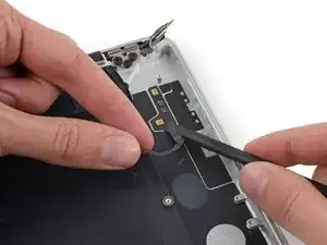
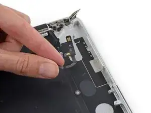
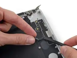
    • Ziehe das Mikrofonkabel vorsichtig nach oben und schiebe gleichzeitig das flache Ende eines Spudgers unter das Kabel, um den Klebstoff zu lösen, mit dem es am oberen Gehäuse befestigt ist.

    • Entferne das Mikrofonkabel.

    New top case comes from Apple with the microphones/cable assembly already in place.

    Jeff Cook -

Abschluss

Um dein Gerät wieder zusammenzusetzen, folge den Schritten in umgekehrter Reihenfolge.

Andrew Optimus Goldheart

Mitglied seit: 17/10/09

493952 Reputation

Ein Kommentar

Dear Andrew,

Thank you so much for an amazing guide. The only trouble I have is sourcing the part. The only microphones I can find online are 2012-2013 compatible models.

Apple Part #:

923-0100

Manufacturer Part #:

821-1571-A

Are these the same part, and if not do you by any chance have a suggestion for finding the correct part number?

Best regards,

Rob
Rob Smith -