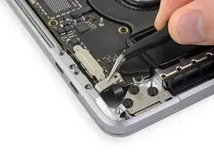
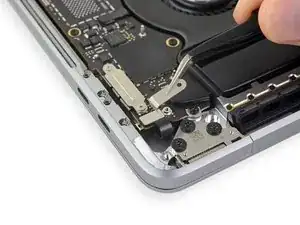
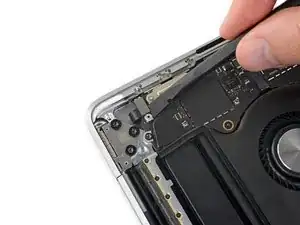
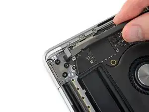
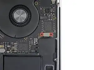
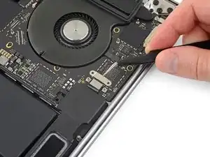
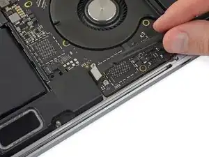
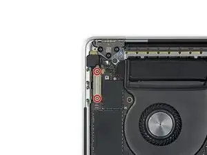
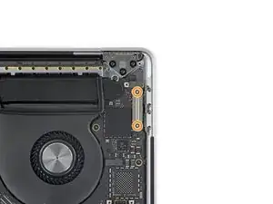
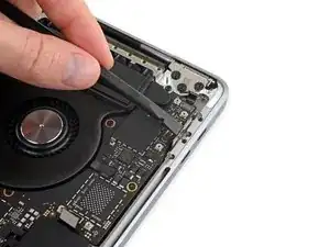
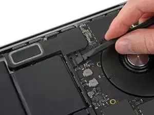
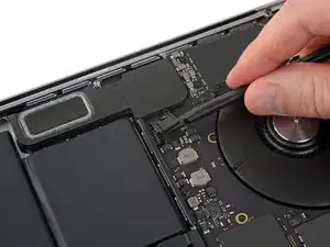
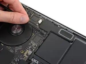
Einleitung

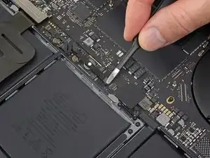
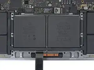
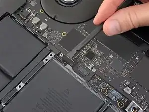
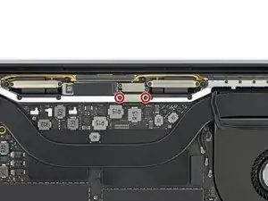
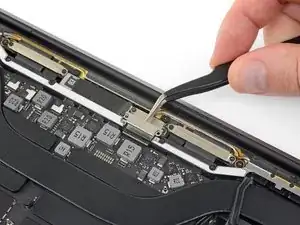
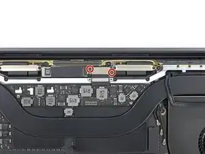
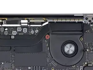
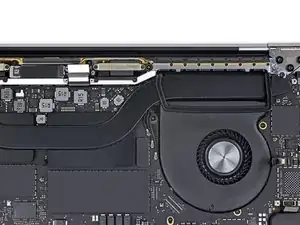
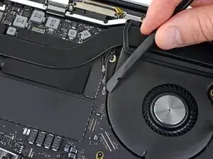
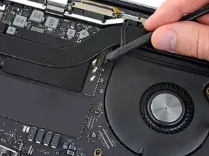
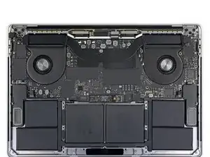
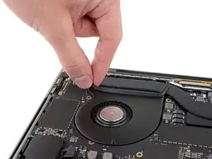
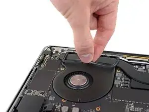
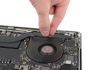
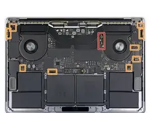
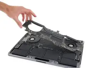
Nur grundständige Anleitung - Anhand dieser Anleitung kannst du das Logic Board und den Kühlkörper vor der Reparatur zusammen als Einheit entfernen.

  1. dLTjRC36EADiCFBK
    dLTjRC36EADiCFBK
    FZYKkYtpGq1QwBO2
    YAOsWGKtCtOGVFRy
    • Zuallererst musst du die automatische Startfunktion (Auto Boot) deines Macs deaktivieren. Auto Boot schaltet deinen Mac ein, wenn du ihn aufklappst, was versehentlich beim Auseinanderbau passieren kann. Benutze diese Anleitung oder befolge die anschließende Kurzversion zum Deaktivieren von Auto Boot. Dieser Befehl funktioniert eventuell nicht auf allen Macs.

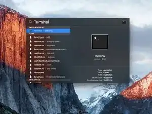
    • Schalte deinen Mac ein und starte Terminal.

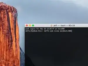
    • Kopiere den folgenden Befehl und füge ihn im Terminal ein (oder tippe ihn exakt so ein):

    • sudo nvram AutoBoot=%00

    • Drücke die Eingabetaste [return]. Wenn du dazu aufgefordert wirst, gib dein Administratorpasswort ein und drücke erneut [return]. Hinweis: die Return-Taste kann auch mit ⏎ oder "enter" gekennzeichnet sein.

    • Nun kannst du deinen Mac sicher herunterfahren und das untere Gehäuse öffnen, ohne dass er sich versehentlich einschaltet.

    • Nachdem deine Reparatur zu Ende ist und dein Gerät wieder erfolgreich zusammengebaut ist, musst du Auto Boot mit folgendem Befehl wieder aktivieren:

    • sudo nvram AutoBoot=%03

    Is this step necessary? I can’t perform this step as I am attempting to repair water damage and need to remove logic board & most likely replace the battery.

    Macrepair SF -

    @mac_medic You definitely don’t want the power coming on while the board is wet. In your case, I think powering on the machine to disable Auto Boot would do more damage than it prevents. I agree, skip this step and be prepared to disconnect the battery quickly if the laptop automatically powers on. Good luck!

    Jeff Suovanen -

    Thats right! You don't want power running while working on your logic board.

    Dan -

    This did not work when running High Sierra.

    Kyle B -

    Tried this on a 2018 MBP 13” Touchbar (there’s no iFixit guide for this model yet). Need to replace a broken screen.

    Luckily I managed to connect to an external screen (Cmd-Down Brightness to switch displays) and enter above command. Seems to work, but there’s another problem with this model - it powers up as soon as any key is pressed……. ffs <gnashes teeth>

    Cool_Breeze -

    I unscrew the battery first and wrap electrical tape over the logic board battery connector before attempting any repairs to the board. Haven’t had any problems yet and I’ve worked on about 10 of these models already. Also when you open the bottom case use a suction cup at the bottom and pull up then run a plastic spudger along the edges to disconnect the clips. Also only use a plastic spudger on the board. Saw a youtube video from a repair shop and he did not disconnect the power and used all metal tools during the entire process of removing the board. His last step was to disconnect the battery terminal.

    Brian -

    Is this step necessary if my mac can turn on? Battery fully dead(

    Nursat b -

    BEFORE YOU START: The included torx head stripped off before I was done (and you might need an additional T4) so stop now and go buy a good one. Also they fail to warn you above to get some blue threadlocker ahead of time.

    Jason Sherron -

    This command did not work for me and I read that sometime in later 2020 Apple stopped this command from working…any ideas on a work around?

    Patrick Machacek -

    Not able to do that with damaged screen

    richardjgreen -

    If you have a damaged screen you can still use a converter from thunderbolt (USB 3) to HDMI and plug your Macbook Pro to your TV as monitor display. Just make sure to chose the right Source (HDMI IN) in your TV. I did it and to make it work I unplug and plug again in my Macbook and so I could disable the Auto boot

    Roberto Sanchez Bustos -

    Hi. This does not work on 2018 13” MacBook Pro with Touch Bar. I did exactly this to disable auto boot. But when I check by using nvram -p it says: auto-boot true. Am I doing something incorrectly? I did everything step by step. Copied and pasted the sudo command, pressed enter and then entered my password. I have Big Sur 11.1 installed. Is there any other way since I need to replace the screen. Thank you. Adrian

    Adrian Vizik -

    Hi everyone. This is also a little pointless if you can’t see anything on the screen, and you don’t have a display adapter to USB C to display it. I agree with Brian about removing the back and disconnecting the battery cable before you even think about opening the lid of the MacBook. Applying the insulation tape is also a handy little tip that just makes sure there is no way to discharge from either the board or battery.

    Roberto Enrieu -

    running `nvram -p | grep 'AutoBoot'` in terminal verifies that it was accepted

    result: `AutoBoot %00`

    Marek Polák -

    Running Big Sur 11.6.7 on a 2019 16" MBP, it's "auto-boot". So it's: nvram -p | grep 'auto-boot' to display the current state, the default is true - and then to change it, sudo nvram auto-boot=false which turns it off.

    Ed Mechem -

    This step is completely unnecessary if you follow the guide to disconnect the battery properly. Just put some tape between the battery and logic board connection to prevent it from accidentally touching and therefore powering on the laptop.

    Grant Ormsby -

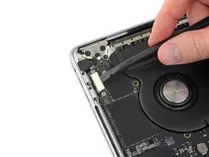
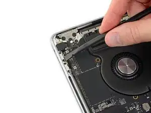
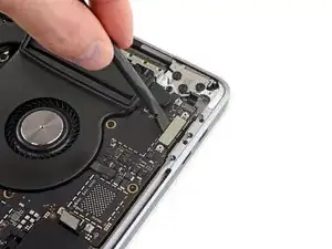
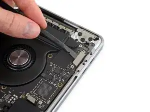
    It took me a few tries to make this command work, as I was able to copy and paste the command into Terminal, but could not type in my laptop’s password. I finally typed my password into a text document, copied it (command C), and then pasted it into Terminal and it worked.

    tommy404 -

    I didn’t do this. Mine never auto-booted before I replaced the battery. Now it does.

    hatuxka -

    BEFORE YOU DO ANYTHING - CHECK THE BATTERY!

    I-fixit sent me a bad battery, which I didn’t realize until it was already install. They sent me a new one, but I wasted hours uninstalling and reinstalled.

    Get a volt meter and measure the voltage on the output of the battery pack. If it reads 0 V, SEND IT BACK. It should read over 2 V.

    bcardanha -

    When I did this from Terminal.app within Recovery Mode, the “sudo” was not recognized but I could invoke it without the sudo part. It seems to have been accepted when looking at “nvram -p”

    johann beda -

    When in Recovery Mode, you already have superuser powers. So you don't need to prefix commands with the sudo command to invoke them with root privileges; you already have them. Do a pwd (print working directory) after opening Terminal in Recovery Mode, and you'll see that you're in the root user's directory.

    Ed Mechem -

    I received the battery kit for my 2018 MacBook Pro and as per the above comment from bcardanha - Oct 12, 2021, I checked the voltage on the pads marked + and - . It was zero volts so I panicked a bit.

    I sent a message on the iFixiT Facebook page and I got no reply. I finally found the customer service email for Ifixit Europe and sent them an email voicing my concern as I was not keen to work for couple of hours just to discover that the battery is faulty. I had an almost instant reply on the email (kudos to them) and they adviced me to go ahead and install the new battery as the voltage measured when battery is not connected is not relevant.

    I took a leap of faith and after two hours… the new battery showed 50% charge and everything seems to be working just fine. I am happy it worked.

    Mircea Comanici -

    After removing the old battery and installing the new battery I powered up the MBP before screwing the bottom on. I discovered the my keyboard would not function. It took a few hours of investigation and frustration that I discovered the track pad power ribbon had become partially dislodged from the trackpad. I was able to see that this through the little machined slot where the battery sat. I had to remove the trackpad to reinsert the power ribbon back into the connector in the trackpad. after reassembling and reinstalling the battery etc the keyboard worked. Just food for thought if your run into the keyboard issue.

    Ed Mease -

    This should be the default. IMO I tell you to power on - not the lid.

    G Sena -

    Est ce que cela fonctionne sur un macbook pro 2017 sans touchbar ?

    maël muzelet -

    Bonjour Maël, oui, ce tutoriel concerne "les MacBook Pro 2016 (et plus récents) et les MacBook Retina 12" 2017 (et plus récents)"

    Claire Miesch -

    Excellent instructions. I was able to follow and install the new screen. I recommend that you get a good set of tools before you begin. I started with an inexpensive repair kit bought online. The Penta and torx bits failed. I bought an IFIXIT kit with quality bits and I was able to do everything I needed.

    Tom Markham -

    If you're not running an admin account the sudo command won't work (which honestly, you should not be running admin). Rather than logging in to your admin amount via the OS, in the terminal type "login [admin username]," then the password and you'll be able to do the sudo command as described above. Once you're complete, type "logout [admin username]" and you'll be good to go. Obviously replace [admin username] with whatever the account name for your admin user is.

    arichard2401 -

  2. 5iYIgSZgIU6hkP1B
    5iYIgSZgIU6hkP1B
    UVKOsGSvaL1OsSL3
    • Schalte dein MacBook Pro vollständig aus und ziehe den Stecker aus der Steckdose, bevor du anfängst. Schließe das Display und drehe den Laptop um.

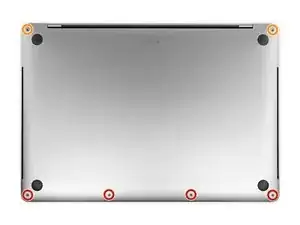
    • Entferne mit einem P5-Pentalobe-Schraubenzieher die sechs Schrauben, mit denen das untere Gehäuse befestigt ist:

    • Vier 4,7 mm Schrauben

    • Zwei 6,6 mm Schrauben

    • Du wirst sehen, dass die Schrauben in einem leichten Winkel herauskommen. Du musst sie dann später auch genau so wieder einsetzen.

    • Merke dir gut, wo welche Schraube war und vergewissere dich, dass du sie wieder genau dort eindrehst, wo du sie herausgedreht hast, um Schäden an deinem Gerät zu vermeiden.

    I miss a printable template to leave the screws and removed parts on it for future identification when reassembly, linked maybe with the location in the Macbook, or with the number of the step.

    Juan Ignacio Fernández García -

  3. ijkfCfPMSRX2ALo2
    ijkfCfPMSRX2ALo2
    5CkAq3GH4yfvDTM5
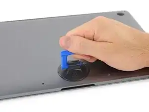
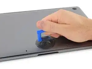
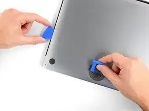
    • Drücke den Saugnapf in der Nähe der Vorderkante auf das untere Gehäuse zwischen den Schraubenlöchern.

    • Ziehe den Saugnapf gerade so weit nach oben, bis eine kleine Lücke unter dem unteren Gehäuse entsteht.

  4. 3tccyXXDSgVUfV5r
    3tccyXXDSgVUfV5r
    dGSZtjC2B25WfTqZ
    LkbLcUdZnPtyUlDZ
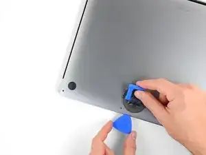
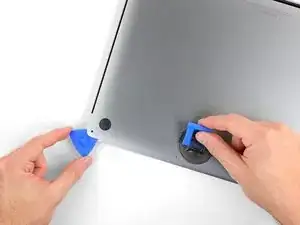
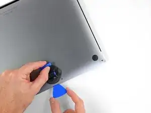
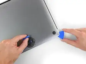
    • Schiebe die eine Ecke eines Plektrums in die entstandene Lücke.

    • Schiebe das Plektrum um die nächste Ecke und dann zur Hälfte über die Seite des MacBook Pro.

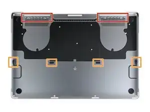
    • Dadurch wird der erste der verdeckten Clips freigegeben, mit denen das Gehäuse gesichert ist. Du solltest den Clip erfühlen und ihn klicken hören.

  5. HOVvMHuquXdBar2x
    HOVvMHuquXdBar2x
    oFJCHJDsnpdUHHUU
    ODWHnoCuXGXGKJla
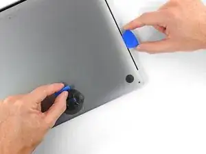
    • Wiederhole den vorherigen Schritt auf der anderen Seite und verwende das Plektrum, um den zweiten Clip zu lösen.

  6. cuTtNQlkiufuESrG
    • Hebe die Vorderkante des unteren Gehäuses (die dem Displayscharnier gegenüberliegende Seite) so weit an, dass du mit den Fingerspitzen darunter gleiten und es gut greifen kannst.

    • Zwei zusätzliche verdeckte Clips in der Mitte der Abdeckung können an dieser Stelle klicken und sich öffnen, sofern dies noch nicht geschehen ist.

    • Hebe nicht zu weit an und versuche noch nicht, das Gehäuse vollständig zu entfernen.

  7. rXaRTOtGXtFtIpF5
    rXaRTOtGXtFtIpF5
    AlvVmxKf6DlNLakh
    WJMFC2MdulDBxoXv
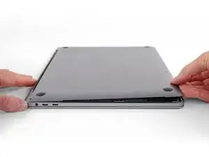
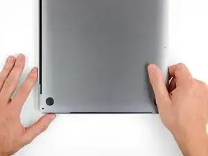
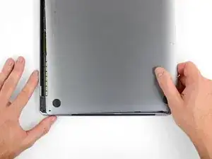
    • Ziehe das untere Gehäuse fest in Richtung der Vorderkante des MacBook (vom Scharnierbereich weg), um die letzten Clips zu lösen, mit denen das untere Gehäuse gesichert ist.

    • Ziehe zuerst an einer Ecke und dann an der anderen.

    • Zur Seite ziehen - nicht nach oben.

    • Das könnte ziemlich viel Kraftaufwand bedeuten.

    With the amount of force needed to carefully pull the back panel out, this caused the back panel to scratch the battery. I don't see or hear any expansion, but this still has me concerned.

    gladgura -

    this step must require a lot of force. I tried to pull it with the plastic hookie thing from the ifixit set by hooking it in one of the screw holes — the tip of the hookie thing broke.

    Oleksii Toldaiev -

    The amount of force required for removing the bottom cover is absolutely ridiculous. Almost feels like i'm about to push my MacBook towards the wall the second it comes off.

    Be careful, I ended up breaking 2 grounding pins on the motherboard last time I tried opening my computer up.

    techtalkf -

    PLEASE DON'T PULL!!!

    Instead just gently push with plastic pick from the other side (where vents outputs are) towards the center... Cover will very easily open that way.

    I hope iFixit will correct this step.

    Kamil Roman -

    Came here to share exactly this.

    Robert -

    That's definitely how this step should be done. Thanks!

    VovS -

  8. 1eexZLVG2E3kwXhw
    1eexZLVG2E3kwXhw
    Koax55WG2pDjZ1MC
    WUXJn5rl13iOX11X
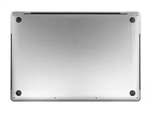
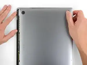
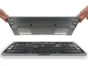
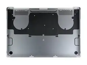
    • Entferne das untere Gehäuse.

    • So baust du das untere Gehäuse später wieder ein:

    • Lege es in Position und richtedie Clips in der Nähe des Displayscharniers aus. Drücke die Abdeckung nach unten und schiebe sie zum Scharnier. Es sollte nicht mehr rutschen, wenn die Clips einrasten.

    • Wenn die Clips vollständig eingerastet sind und das untere Gehäuse korrekt ausgerichtet ist, drücke fest auf das untere Gehäuse, um die vier verdeckten Clips darunter einzurasten. Du solltest fühlen und hören, wie sie einrasten.

    If I had it all to do over, again, I would blow out the dust with compressed air at this point. During the disassembly, I kept encountering little dust bunnies, and I was very worried that one would get caught in one of the connectors when I plugged everything back up (which wouldn’t get discovered until I put it all back together and tried out all of the components).

    Joe Emenaker -

  9. PTIZqDdpESIEg6iK
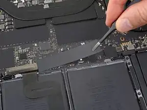
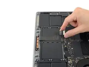
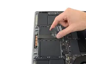
    • Ziehe den isolierenden Aufkleber auf der Akkuplatine an der der Akku nächstgelegenen Kante des Logic Board ab und entferne ihn.

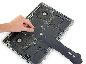
    • Wenn sich die Abdeckung nicht leicht ablösen lässt, erwärme sie mit einem iOpener, einem Haartrockner oder einer Heißluftpistole, um den darunter befindlichen Klebstoff aufzuweichen, und versuche es erneut.

    • Wenn die Abdeckung beim Zusammenbau nicht sicher sitzt, drehe sie um 180 Grad. Sie muss richtig ausgerichtet sein, damit die darunterliegenden Klebepads die Schrauben vom Board berühren.

  10. MZhqvhivJc6ltuBI
    MZhqvhivJc6ltuBI
    a5jICxWI6SwpreQK
    ur1oBPkypLAwkAay
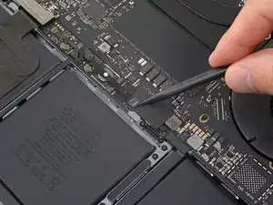
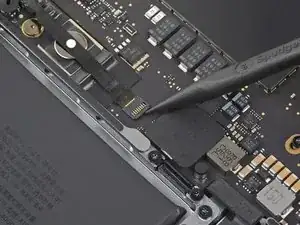
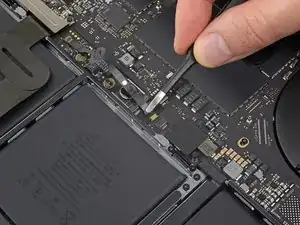
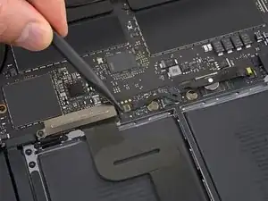
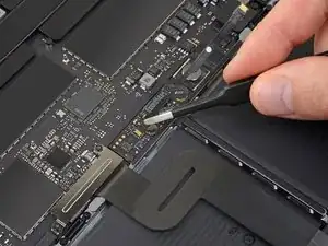
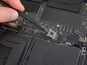
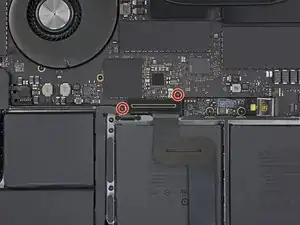
    • Ziehe das Klebeband vom Anschluss des Datenkabels der Akkuplatine ab.

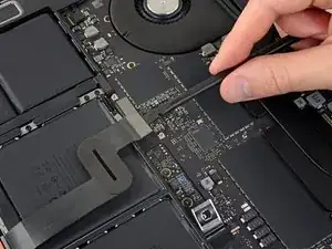
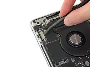
    • Heble mit einem Spudger vorsichtig die Verriegelungsklappe am ZIF-Anschluss für das Datenkabel der Akkuplatine auf.

  11. SBuNWrrEsnEHWE5U
    SBuNWrrEsnEHWE5U
    WSVYglC4kJSVXbLA
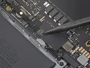
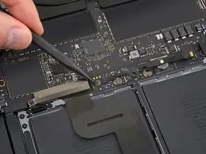
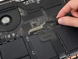
    • Trenne das Datenkabel der Akkuplatine, indem du es aus der Buchse auf dem Logic Board ziehst.

    • Schiebe parallel zum Logic Board in Richtung des Kabels.

  12. 3QMLTKDDDaOIEXZk
    3QMLTKDDDaOIEXZk
    QJeqYMjSJObGSxLc
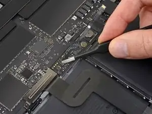
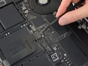
    • Heble die Verriegelungsklappe am Stecker am gegenüberliegenden Ende des Datenkabels der Akkuplatine auf und trenne sie.

  13. doyrMkF4Ol2fsUCf
    doyrMkF4Ol2fsUCf
    FlF4ZwiPrAxEkwSi
    • Schiebe das Datenkabel der Akkuplatine aus der Buchse auf der Akkuplatine und entferne es vollständig.

    • Achte darauf, dieses Kabel nicht verkehrt herum oder falschrum zu verlegen. Bei korrekter Installation sollte der weiße Aufkleber mit der Flüssigkeitsanzeige nach oben zeigen und direkt über der Verbindungsschraube des Akkus positioniert sein.

    Bonjour, super Tuto, petite question elle sert a quoi cette nappe , et quesqui se passe si elle est pas branché ?

    Jorgio -aigleBrun- -

  14. YCrvX4dDTLFRo2He
    YCrvX4dDTLFRo2He
    REFmgM15LSgj5I14
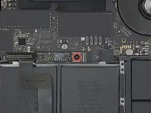
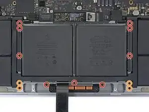
    • Entferne mit einem T5-Torx-Schraubendreher die 3,7-mm-Flachkopfschraube, mit der der Akkustecker befestigt ist.

  15. rmLuSU2NmsUdQIQp
    rmLuSU2NmsUdQIQp
    aMGREyB4myE324Ug
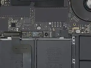
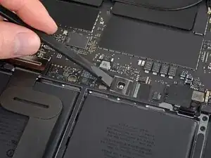
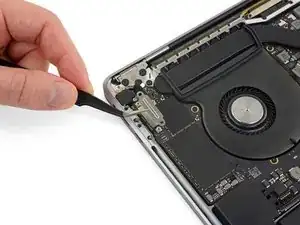
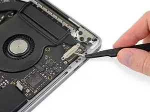
    • Verwende einen Spudger, um den Akkustecker anzuheben und den Akku abzuklemmen.

    • Hebe den Stecker hoch genug, um ihn während der Arbeit von der Buchse zu trennen. Wenn es versehentlich zu Kontakt kommt, kann dein MacBook Pro beschädigt werden.

    Put a little bit of insulating tape over the terminal to be safe.

    Brian Tibbels -

  16. sK4lqBHxryavnDid
    sK4lqBHxryavnDid
    oF22XSHRWEFwHmoR
    • Entferne mit einem T3-Torx-Schraubendreher die beiden 1,9-mm-Schrauben, mit denen die Abdeckungshalterung für die Tastatur- und Trackpad-Kabelanschlüsse befestigt ist.

    • Entferne die Halterung.

  17. ncIQWCHpRGO1fSb2
    ncIQWCHpRGO1fSb2
    yKukLfBQSF5SR1va
    • Verwende einen Spudger, um das Trackpad-Kabel zu trennen, indem du den Stecker gerade vom Logic Board abhebelst.

  18. noPvQ2CLs1jptX2p
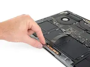
    • Erwärme das Trackpad-Flachbandkabel ein bisschen, um den Klebstoff, mit dem es am Akku befestigt ist, aufzuweichen.

    • Dazu kannst du einen iOpener, einen Fön oder eine Heißluftpistole verwenden. Achte aber darauf, den Akku nicht zu überhitzen. Das Kabel sollte warm sein, aber nicht zu heiß zum Anfassen.

  19. bRNYL1JeZ2MUeBe2
    bRNYL1JeZ2MUeBe2
    XJTjmkOpAHj1XPso
    irj3TcmYrfGAxaAU
    • Ziehe das Trackpad-Kabel vorsichtig vom Akku ab und schiebe es zur Seite.

    • Kabel nicht knicken oder reißen. Wenn du Probleme hast, versuche nicht, sie mit Gewalt zu lösen, sondern erwärme nochmal und versuche es dann erneut.

  20. JDrgfAWr1UO6RLKu
    JDrgfAWr1UO6RLKu
    tCIssjKYVvECMJsB
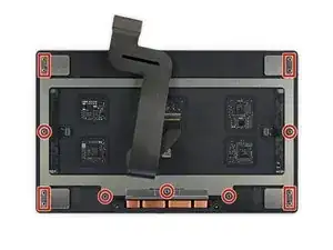
    • Entferne mit einem T5-Torx-Schraubendreher die 13 Schrauben, mit denen die Trackpad-Baugruppe befestigt ist:

    • Neun 5,8 mm Schrauben

    • Vier 4,9 mm Schrauben

    • Diese Schrauben sehen alle ähnlich aus - achte darauf, sie nicht zu verwechseln.

    • Wenn du beim Wiederzusammenbau ein bisschen blaues Schraubensicherungsmittel aufs Schraubengewinde gibst, kannst du verhindern, dass sich die Schrauben im Laufe der Zeit lösen.

    • Bringe die Schrauben zunächst locker an und überprüfe dann die Ausrichtung des Trackpads, bevor du sie festziehst.

    I dont have the “clicky” feedback from my trackpad anymore - please advise how to fix this

    Shadi Saif -

    (MacBook Pro 2019 15” 2 years old) There are 4 screws (2 on the left and 2 on the right, each pair held down by a black metal piece) next to the uppermost 5.8mm screws. What is the size/kind of screw are these? I’d like to purchase these missing items? Please help. A suspicious technician tried to scam me out of money. I asked for my computer back before they could charge me. I decided to do the repairs myself. When I received my laptop back and followed Ifixit instructions I found 2 screws missing and they replaced the original with an unrecognizable rusty screw on the farthest left screw hole, and the black metal pieces were missing as well.

    Alathia Kaye -

  21. dbGJfyNAFLmgI6OQ
    dbGJfyNAFLmgI6OQ
    d31aHAXyDOBZbn6q
    WVy1FAO3B2SbT1ie
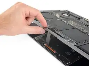
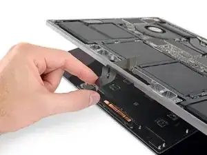
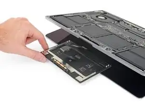
    • Klappe das Display leicht auf, aber halte das MacBook immer noch verkehrt herum. Die Trackpad-Baugruppe sollte sich trennen und flach auf dem Display liegen.

    • Führe das Flachbandkabel des Trackpads vorsichtig durch den Schlitz im Gehäuse.

    do not turn the touchpad over, as there are 4+5 very thin spacers/washers, and you might lose them. only the next step warns you about this. dont be me!

    George Kiss -

  22. yIm1JNUtPSAhyjoc
    yIm1JNUtPSAhyjoc
    AqeMok2AxKKOdhLZ
    NHbfjLZpScjEKpF5
    • Achte beim Entfernen der Trackpad-Baugruppe darauf, dass du die neun kleinen Metallscheiben nicht verlierst, die auf den Schraubpfosten aufliegen. (Sie werden herausfliegen und sehr leicht verloren gehen.)

    • Entferne die Trackpad-Baugruppe.

  23. ZWY2wWJIA2sohYJR
    ZWY2wWJIA2sohYJR
    VOv2slGFGMLOQBFe
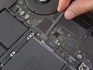
    • Verwende deinen Spudger, um die Tastatur zu trennen, indem du den Stecker gerade vom Logic Board abziehst.

  24. 2ACOrmEBuVLGGMxV
    2ACOrmEBuVLGGMxV
    ESJgAWhAIByUZn5u
    • Entferne mit einem T3-Torx-Schraubendreher die beiden 3,5-mm-Schrauben, mit denen die Abdeckung am Flexkabel des Display Boards befestigt ist.

    • Entferne die Abdeckung des Display Boards.

    I was able to complete this procedure successfully without removing the logic board. I don’t use any liquid adhesive remover. I employ A rubber type silicon rubber-semi stiff spatula used for putting icing on cakes. Use careful leveraged prying, sliding under battery to break the adhesive seal. Also careful application of heat with a heat gun being careful to not damage the speakers. I remove all logic board screws, disconnect all service cables including USB C caps on both sides. The goal is to be able to carefully ”lift” The lower edge of logic board most proximal to the battery enough to allow the ribbon cable to clear the “ridge” that is on rear edge of the battery compartment, Thus allowing you to pull the battery back horizontally towards The front edge laptop and out. I use popsicle sticks to keep the logic board lifted. Careful not to bend the board or break it! You need about 1/8” of clearance. 99% isopropyl alcohol libera dabbed on with a Q-tip to adhesive residue will clean it off.

    Macrepair SF -

    I had some issues using my T3 bit for most of these screws. Had to use a T4. Strange because I do not use either of those bits often, so I would assume they are still in good shape. Using a T3 felt like I was going to round out each of the screws. Wonder if anyone else experienced this same thing? I'm using the 'Pro Tech Toolkit' by iFixit.

    Michael Stein -

  25. h3LUEOUmG1Qa4FHB
    h3LUEOUmG1Qa4FHB
    jTMKbKYBPoyAAij6
    • Entferne mit einem T3-Torx-Schraubendreher die beiden 1,7-mm-Schrauben, mit denen die Halterung für den Kabelanschluss des Display Boards befestigt ist.

    • Entferne die Kabelanschlusshalterung des Display Boards.

    Help! I stripped the T3 Screw!! ?

    J S -

    I also did this

    jerryrobsonjr -

    Both of these screws also stripped for me. I’m not sure taking extra care would have helped: they stripped almost instantly and felt corroded. I basically continued by carefully manually turning out the right screw head using a regular, (slightly larger than T3) philips driver (and other small tools) until the head popped off the screw and one side of the bracket released. Then the bracket can be lifted and the other screw can be loosened using upward pressure. Upon replacement I basically used a small amount of high viscosity “gel” super glue (or epoxy) to reattach the right side of the bracket.

    capecodnative -

    Ok, I stripped it too. Feels like it isn't a t3 screw... Using the t3 bit from ifixit kit. Have a bite when turning clockwise but won't bite counter clockwise

    Chi Wang -

    Tried with another T3 bit (was using the T3 bit from ifix battery kit) and manage to remove one screw. The other one stripped too much but followed the recommendation from above comment about lifting the bracket

    Chi Wang -

    And now? It's definitely not T3. What the hell do I do now...

    Marina Llopis -

  26. hWNUVuXxYGkOQLuW
    hWNUVuXxYGkOQLuW
    3lW4x2iOsthCyeb2
    • Hebe das Flexkabel des Display Boards gerade aus der Buchse, um es vom Display Board zu trennen.

  27. NGFfbbntTcLfE6AN
    NGFfbbntTcLfE6AN
    TLBZSWgTQu1TCaxo
    • Entferne mit einem T3-Torx-Schraubendreher die vier 2,0-mm-Schrauben von den Scharnierabdeckungen (zwei Schrauben auf jeder Seite).

  28. WESQjibowRGIOB4y
    WESQjibowRGIOB4y
    VQnIDOppIXlPfvOS
    dIZRRRhATdIGluks
    • Entferne die beiden Scharnierabdeckungen.

  29. qxkZlsQjNTiqcykg
    qxkZlsQjNTiqcykg
    xxSD5pgXaB5CtOjl
    qEuLVDOGNShUMJU4
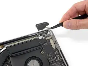
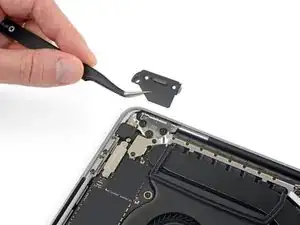
    • Entferne mit einem T3-Torx-Schraubendreher die beiden 2,4-mm-Schrauben, mit denen die Abdeckungshalterung für die Touch ID- und Kopfhörerkabelanschlüsse befestigt ist.

    • Entferne die Halterung.

    Here is a first! I did not notice this when disassembling but spent a bit of time validating I had reassembled things correctly. After 35 years of this stuff, you don’t see much new - just smaller. !

    —->The 2.4 mm screw closest to the hinge screws into the logic board screw circled in green T8 (larger head)at step 47.

    Try finding that screw in your bucket of spares!

    Brian Eustis -

  30. K5fPx6JlRJOUXRMt
    K5fPx6JlRJOUXRMt
    k4hHBkxVZcreXFY6
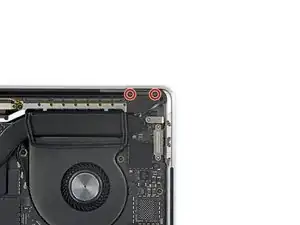
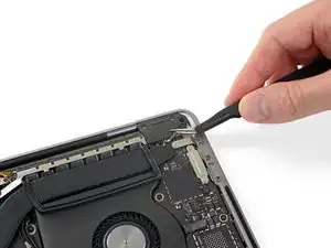
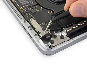
    • Trenne den Anschluss der Kopfhörerbuchse, indem du ihn gerade vom Logic Board abhebelst.

  31. LAcQL4JQvGZYGWGU
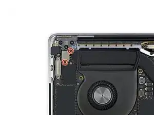
    LAcQL4JQvGZYGWGU
    GWgliFUh24bmRuLB
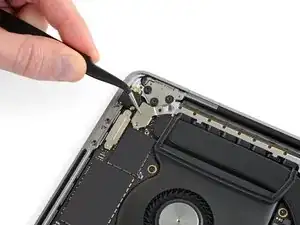
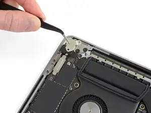
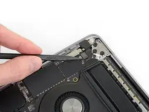
    • Trenne den Netzschalter und den Touch ID-Sensor, indem du den Anschluss gerade vom Logic Board abhebelst.

    This smaller connector cable of the touch ID sensor that sits underneath the power sensor connector is easy to overlook when replacing the logic board. It is small & short and can easily hide. Make sure you account for it when placing the LB in and before screwing it down.

    Macrepair SF -

  32. JxwuAZXOHeF3CfYO
    • Entferne mit einem T3-Torx-Schraubendreher die 1,3-mm-Schraube, mit der die Abdeckungshalterung für den Touch Bar-Digitizer-Anschluss befestigt ist.

  33. gjGOmxTJPlV5Pcoi
    gjGOmxTJPlV5Pcoi
    ajmGXYArtoeYfTZx
    BQ33qY5wqiop1X2p
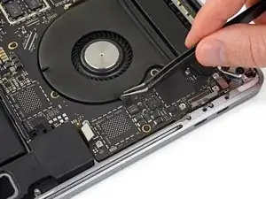
    • Schiebe die Halterung mit deiner Pinzette in Richtung der Seitenkante des MacBook Pro, bis die geschlitzte Haltelasche auf dem Logic Board frei ist.

    • Entferne die Halterung.

  34. OLEyZERLrZmuCWOc
    OLEyZERLrZmuCWOc
    YtBrywD3Z46KJOeH
    • Trenne das Touch Bar-Digitizerkabel, indem du es gerade vom Logic Board abhebelst.

  35. Z4WLmC4Af1MgSPwC
    Z4WLmC4Af1MgSPwC
    TBEkxgCdmTZxTq3D
    • Entferne mit einem T3-Torx-Schraubendreher die beiden 1,9-mm-Schrauben, mit denen die Halterung für den Touch Bar-Displaykabelanschluss befestigt ist.

    • Entferne die Halterung.

  36. rdtc2HfFhemuFkP5
    rdtc2HfFhemuFkP5
    V1lJDfNAwoMJh5VT
    • Trenne das Kabel des Touch Bar-Displays, indem du den Stecker vom Logic Board gerade nach oben abziehst.

    Right above the connector, there might be a chip attached instead of an empty space as shown in the photos. The connector will be close to the part but they are separate, and the connector can be safely removed.

    yqy980210 -

  37. Zg64coNjUyXMTLDc
    Zg64coNjUyXMTLDc
    sfFumwaPW4PM65rF
    • Nimm einen T3-Torx-Schraubendreher zur Hand und entferne:

    • die beiden 1,3-mm-Schrauben, mit denen die Thunderbolt-Flex-Kabelabdeckung links befestigt ist.

    • zwei weitere 1,3-mm-Schrauben von der Thunderbolt-Kabelabdeckung auf der rechten Seite.

  38. 3knbjJPAymkOLNCS
    3knbjJPAymkOLNCS
    y3lqPE4HW5nqZoLc
    • Entferne die Halterungen der Abdeckungen von beiden Thunderbolt-Kabelbuchsen.

  39. exkgTpYLnlrp4ZZQ
    exkgTpYLnlrp4ZZQ
    AjPJJxTGA5lLBtP5
    EMn4AYmTfpTaIJEl
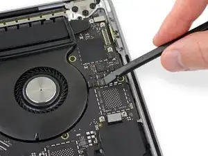
    • Trenne das linke Thunderbolt-Flexkabel mit einem Spudger, indem du es gerade vom Logic Board abhebelst.

    • Heble von der Innenkante her, die dem Lüfter am nächsten ist.

    • Schiebe den Stecker des Flexkabels vorsichtig zur Seite, damit es beim Entfernen des Logic Boards nicht im Weg ist.

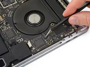
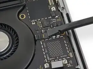
  40. LLsCNB1DthkUlIUN
    LLsCNB1DthkUlIUN
    pQTUTCUHTKgBFrqY
    JcyNSZmtHhshuhtq
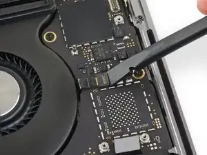
    • Wiederhole diesen Vorgang, um den Stecker des Thunderbolt-Flexkabels auf der gegenüberliegenden Seite zu trennen.

    • Schiebe den Stecker des Flexkabels vorsichtig zur Seite, damit das Logic Board herausgenommen werden kann, ohne dass es hängenbleibt.

  41. JGtZy3HuTUAeBoS3
    JGtZy3HuTUAeBoS3
    dRMCKLupNlCc3a52
    RODaAEUfwKQAvROr
    • Trenne die beiden Lautsprecheranschlüsse, indem du das flache Ende Ihres Spudgers unter jedes Kabel in der Nähe des jeweiligen Anschlusses schiebst.

    • Vorsichtig drehen oder hebeln, um beide Lautsprecher zu trennen.

    Both had a dab of glue underneath. I used heat gun to loosen.

    Macrepair SF -

    On this step, it helped to use the tip of sharp tweezers to open the small metal tab of the connector to the side.

    Rodrigo Damazio Bovendorp -

    After disconnecting the speaker connector, does the speaker just come out, or is it glued or screwed in place? All I need is to Replace the Right Speaker with a New one. This guide gets me to this point but doesn’t address replacing the speaker. Would like to know if it’s more complicated than that before I get started… Thanks

    Would be nice to have a guide just for Speaker Replacement. Thanks

    Chad Gagnon -

    My right speaker doesn't work now because the cable and connector disconnected from the logic board. From one problem to another now... What should I do?

    Blake Johnson -

  42. rpggR1BSd2ivkpCK
    rpggR1BSd2ivkpCK
    Uvg1Erp6vCnduApZ
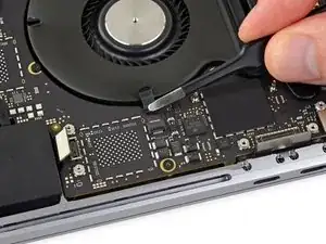
    • Ziehe eventuell vorhandenes Klebeband von der Mikrofonkabelbuchse ab.

    Wenn möglich das Klebeband nicht abziehen! Zwei Schritte weiter bist Du froh darum.

    Stephan Zenger -

  43. jjBThQOLxxBKWtSw
    jjBThQOLxxBKWtSw
    e2dCqFryAVygfQOT
    cZSamwZeQZBWJkFL
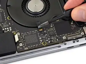
    • Öffne die Verriegelungsklappe am ZIF-Anschluss des Mikrofonkabels, indem du sie gerade vom Logic Board abhebelst.

  44. TBowkAlrNvEIkWWt
    TBowkAlrNvEIkWWt
    kbuC4BITFsryhKqX
    • Trenne das Mikrofon vom Stromnetz, indem du das Kabel Richtung Lüfter ziehst, bis es sich aus der Buchse löst.

    • Ziehe nach Möglichkeit am am Kabel befestigten Klebeband und nicht am Kabel selbst, um die Gefahr einer Beschädigung zu verringern.

  45. 3P3EHShbtOjwWNJh
    3P3EHShbtOjwWNJh
    VHL2DsARcfi1pSAC
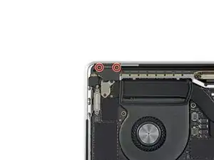
    • Entferne mit einem T5-Torx-Schraubendreher die einzelne 2,9-mm-Schraube, mit der der Antennenkabelstrang befestigt ist.

  46. IxDlbVhlHngl4Cxd
    IxDlbVhlHngl4Cxd
    CKA1yXuOSnccWLUF
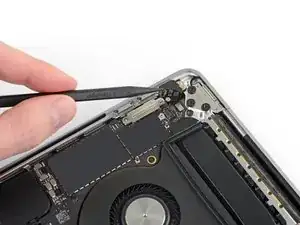
    mjRiQRjFyFmNqOS2
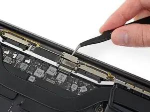
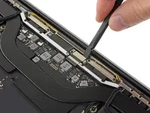
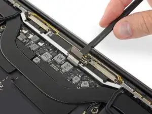
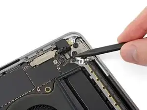
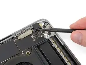
    • Trenne alle drei Antennenkabel, indem du sie gerade aus der Buchse ziehst.

    • Schiebe deine Pinzette oder das flache Ende deines Spudgers unter jedes Kabel, bis es sich in der Nähe der Buchse befindet, und drehe oder heble es dann vorsichtig nach oben, um es zu trennen.

    • Beim wieder Anschließen musst du bei jedem Kabel erst den Stecker direkt über der Buchse ausrichten und dann nach unten drücken, bis der Stecker einrastet.

  47. mdXPZEvBWOLGqRA2
    mdXPZEvBWOLGqRA2
    eMnIAYVCqpZXJAha
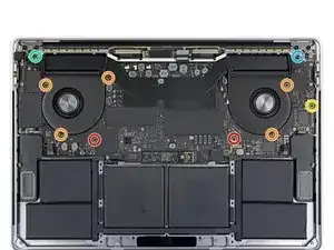
    • Entferne alle zehn Schrauben, mit denen die Logic Board Baugruppe befestigt ist:

    • Zwei 2,6 mm T3 Torx-Schrauben

    • Fünf 2,9 mm T5 Torx-Schrauben

    • Eine 3,7-mm-T5-Torx-Schraube

    • Eine 3,9 mm T8 Torx-Schraube

    • Eine 4,1 mm T8 Torx-Schraube

    • Beim Wiederzusammenbau die Schrauben erst einmal lose eindrehen und dann die Position des Logic Boards überprüfen und gegebenenfalls anpassen, bis alle Anschlüsse ausgerichtet sind. Dann erst die Schrauben fest anziehen.

  48. rCxHE2kgOHPDxy1D
    rCxHE2kgOHPDxy1D
    fkOuMFLayRPhvTCB
    CRooRPymdyPD4OUW
    • Ziehe die beiden Schwingungsdämpfungsstreifen aus Gummi von dem Kleber ab, mit dem sie an den Lüftern befestigt sind, entferne sie aber nicht.

    • Bei Bedarf kannst du einen iOpener, einen Fön oder eine Heißluftpistole verwenden, um den Kleber zu erwärmen und so aufzuweichen, dann wird es leichter, die Dämpfer abzutrennen.

    When replacing the battery, you can leave these, and just lift the logic board, enough so the battery slides out.

    nbeijer -

  49. HpH1yUNwHgwRUfvE
    HpH1yUNwHgwRUfvE
    KbBxQ5UMk2J23kAl
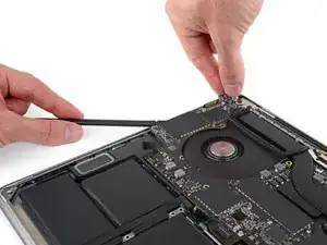
    • Die Baugruppe des Logic Boards sitzt sehr fest, wenn du sie entfernst kannst du dir das Leben leichter machen, indem du einen Spudger unter die linke Kante steckst und ihn leicht anhebst.

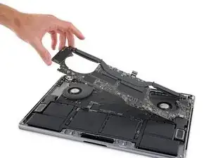
    • Es sollte keinen Widerstand geben, wenn du das Logic Board entfernst. Überprüfe alle Kabel sorgfältig und halte sie bei Bedarf zur Seite, damit sie nicht am Logic Board hängen bleiben.

    • Entferne das Logic Board, indem du es von der linken Seite her abhebst.

    To ease logic board removal (and especially later for reinstallation), I choose to gently bend each connector away from the logic board & use a little tape to hold them out of the way.

    Tech Medic -

    Is there new adhesive for fans? I’m into deep . 50/50 shot.. I get his back together ..😩

    Gerald Rappaport -

    For me, I didn’t have to remove the MOBO. To be honest i didn’t need to follow the steps that require you to remove certain plugs. It may help to remove the speakers and what not, but other than that you don’t have to remove the whole thing. Also this is from my experience. So don’t get mad at me if it doesn’t work. Goodluck!

    Neo -

  50. xWQpLjChkSyWJpL2
    xWQpLjChkSyWJpL2
    NPkZy33WDRtgefPW
    Aonio6YmPc6dyrSi
    • Beim Wiederzusammenbau gehst du folgendermaßen vor:

    • Stelle sicher, dass die Schwingungsdämpfer aus Gummi richtig ausgerichtet sind.

    • Führe den Antennenkabelstrang durch die Lücke zwischen dem Logic Board und dem Kühlkörper und stelle sicher, dass er richtig ausgerichtet ist, wenn du das Logic Board absenkst.

    • Vergewissere dich, dass beim Einsetzen keine Kabel unter dem Board eingeklemmt werden. Überprüfe jede markierte Stelle sorgfältig.

    Would be good to mention (at the end of instructions here) to pay special attention on reassembly that the Touch ID and power button cable does not slip under the logic board at the last moment7

    Wolf Naegeli -

Abschluss

Um dein Gerät wieder zusammenzusetzen folge bitte den Anweisungen in umgekehrter Reihenfolge.
Jeff Suovanen

Mitglied seit: 06/08/13

407169 Reputation

0 Kommentare