Einleitung

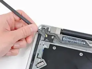
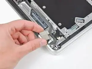
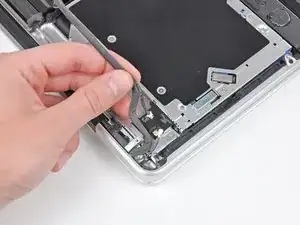
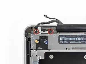
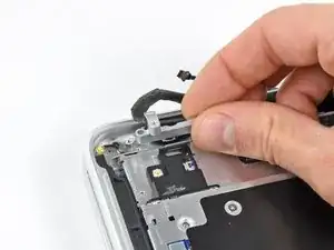
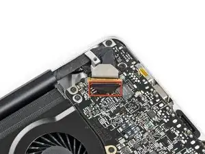
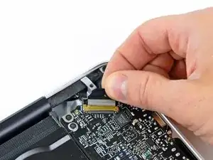
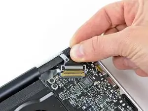
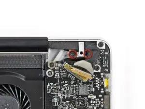
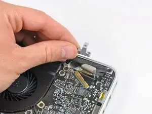
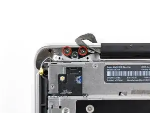
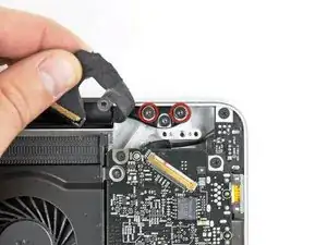
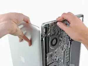
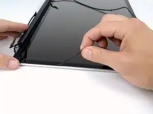
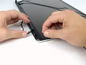
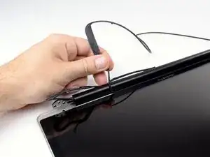
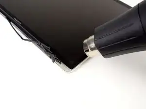
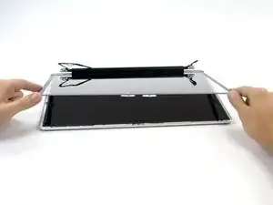
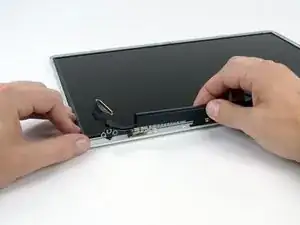
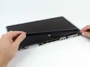
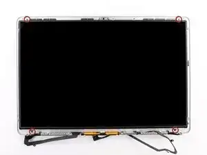
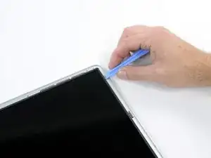
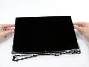
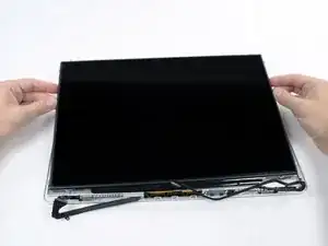
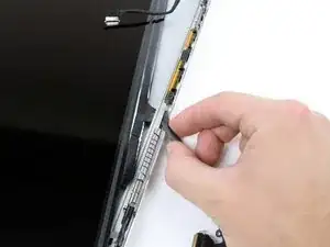
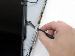
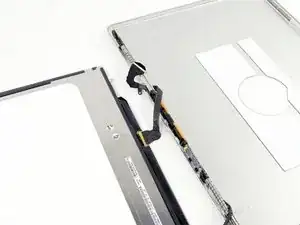
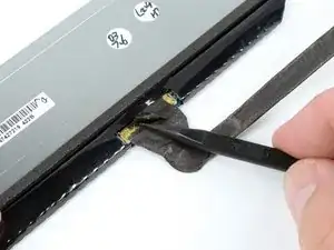
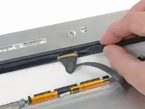
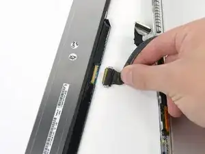
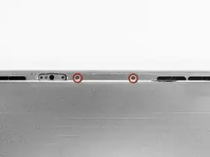
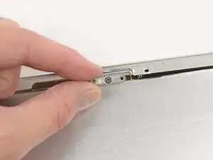
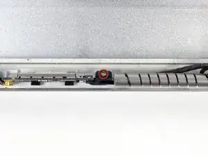
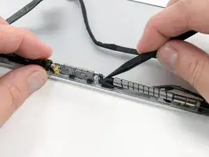
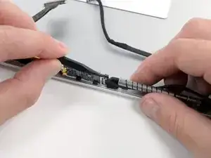
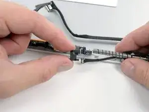
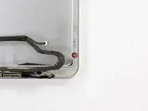
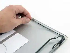
If your camera seems to be acting strange, it may be the fault of the camera cable. If you find that the Wi-Fi connection works only when the display is in a certain position, your camera/AirPort cable may be the culprit. Use this guide to replace a broken or damaged cable.

  1. syE2ybccRrcFeJJi
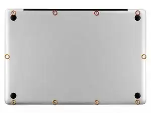
    • Remove the following ten screws securing the lower case to the upper case:

    • Three 13.5 mm Phillips screws.

    • Seven 3 mm Phillips screws.

    important to reassemble the "lower case" successfully: the threads of the seven 3mm phillips screws are drilled at an angle :-/

    mysterioes -

    Same issue with me. After reassembling my 13-inch and my 17-inch, one of the screws are sticking out ever so slightly. Very annoying, especially since I scratch whatever surface I'm on now.

    Kyle Spadaro -

    Very important note; this guide is NOT correct for the Macbook Pro 17" A1297 late '11.

    The A1297 has an assembly adjacent to the optical drive, identifiable by 4 antenna connectors, 1 usb cable (with very small connector) and one PCI-e flat cable running across the optical drive.

    I did not take pictures, but found one on the web. I'm very new to iFixit and have no idea yet on how to create a guide, but here's the picture showing the assembly on top (this pic only has 3 antenna wires, the A1297 has 4, but at least you'll know what to look for.

    - carefully undo all connections and 2 screws

    - remove the assembly and flip it over

    - again carefully remove the shielding tape

    - undo 3 tiny screws

    - gently pry the airport card from the assembly (the flat cable will be a bit of a pain)

    - reverse process with replacement card.

    image can be found here:

    https://dl.dropboxusercontent.com/u/2446...

    Remon -

    It helps if you mark the holes where the long screws go so you can easily find them when the time comes to button things up. Also, a little dish or custard cup to hold those tiny screws is essential.

    Human -

    3 x 13.5 mm screws are actually TWO different types! Return to EXACT SAME HOLES.

    -I discovered this on my mid-2010, but from comments, sounds like it may affect other models as well

    2 x 13.5 mm screws are pointed ends

    1 x 13.5 mm screw is a FLAT end <- CORNER HOLE

    These areTWO slightly different lengths, and must return to correct holes. If you put the flat end screw in the wrong hole, it will stick out slightly. If you put either of the pointed screws in the wrong hole, they will go in all the way, but will not catch threads, and will simply fall out when laptop is flipped back over.

    scottbernardis -

    I printed out the image above and taped each screw to the photo as I removed each one, just to make sure I put them in the right location.

    Grace Morris -

    This is a brilliant suggestion! I did this for all the steps that involved removing screws, numbered the sheets, and that made it very easy to put it all back together in reverse. Thanks!

    Steve Adamczyk -

    Be sure to use Loctite on the screws when re-attaching the bottom of the computer. The screws can and will fall out once they have been removed for repairs if you do not put Loctite on them when you reuse them. Otherwise, purchase new screws before repairing the computer as the new screws come with Loctite material on them. (I have personal experience with this problem.)

    johnpartridge -

    Be sure NOT to Buy this Battery from iFixit. I bought it from eustore.ifixit.com and the Condition of Battery is : Service Battery ,

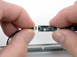
    from the &&^&^$^ first day.

    Till today my battery Cycle Count is: 80.

    I’ve tried everything as: Battery Calibration, resetting the SMC, PRAM, reinstalling the battery,

    and Service Battery warning still there.

    Just DO NOT BUY crappy, trash from here.

    I have very bad experience.

    Doruntin Koci -

    Hi Doruntin,

    we’re more than sorry to hear about your bad experience.

    I’ll inform our customer service team who’ll reach out to you and offer either a replacement or reimbursement.

    If ever you’d need assistance again, please feel free to directly write to eustore@ifixit.com, as comments are not regularly checked for service issues.

    I’m confident that we’ll find the solution that suits you best!

    Sandra Hiller -

    PLEASE OBSERVE: The image of the left speaker used is NOT for a 2011 model. A 17inch MacBook Pro A1297 - LEFT SPEAKER + MICROPHONE - 2011 has IDENTIFYING NUMBER: Apple Part #:922-9821, 922-9822. And its COMPATIBILITY: 17 inch MacBook Pro Unibody A1297 - Early 2011 MC725LL/A 2.2 i7 - Early 2011 MC725LL/A 2.3 i7 - Late 2011 MD311LL/A 2.4 i7 - Late 2011 MD311LL/A 2.5 i7

    kenneth krabat -

  2. FWQlrWBX33M4QNJC
    FWQlrWBX33M4QNJC
    eqC63VPAuJvHpSVE
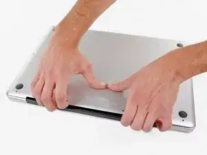
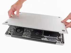
    • Wedge your fingers between the lower case and the vent, and lift upward to release the two clips holding the lower case to the upper case.

    • During reassembly, carefully align the lower case and then press it firmly until both clips engage.

    • Remove the lower case.

    I recommend using anti-static protection, i.e., wearing a ground strap, or at least touch metal chassis inside the computer before unplugging cables. Otherwise, you might create an ESD discharge into your RAM and have to replace it like I did!

    d68ef792 -

  3. IY3hYv13cwDkbBZo
    IY3hYv13cwDkbBZo
    atoPupptXJoHHWsm
    tVLmCpvOQX5JxfZV
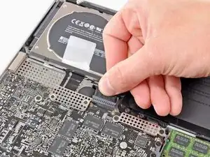
    • Whenever working near the logic board, it is always wise to first disconnect the battery to avoid short circuits.

    • If present, grab the plastic tab attached to the battery connector and pull it toward the front edge of the device. For Late-2011 models the battery connector will not have a tab and is simply a plug that inserts straight down into the motherboard--to remove pry the plug straight up.

    • If the plastic tab is missing, use a spudger to pry the connector up from its socket.

    • Pull the tab parallel to the face of the logic board.

    This step is a little difficult in reverse, that is, when re-attaching the battery. It helps to tilt the laptop up so you can see the edge of the board that accepts the plug. It may look like there are two slots for it, it goes in the bigger slot that is further away from the board.

    yary hluchan -

    Is this step really necessary? It is not part of the instructions how to replace the HDD in Apple's User Manual of the 2011 17" MBP.

    Tobias Hahn -

    As it says in the step: "Whenever working near the logic board, it is always wise to first disconnect the battery to avoid short circuits." It is not required, but it is simple insurance to avoid a $1000+ repair should you accidentally short components on the board with something metal.

    Andrew Bookholt -

    There was no tab on my model. Battery is affixed to board and screws must be removed.

    bhodges2 -

    Mine also, and looks as if removing connector could damage motherboard.

    Stephen -

    The battery on my 17” mid-2010 (MC024LL/A -A1297 ) is held by 3 specialty screws CR-V1 (3-wings similar to Mercedes-Benz tri-star)

    It has a tab which I pulled straight up

    The connector to the motherboard came away easily by pulling toward the front edge.

    Peter Grierson -

    * There is no tab on the A1297 (late 2011) model's battery connector. Be careful with the connector, it chips off the edges easily! Otherwise the same as bhodges2 & Stephen's notes.

    ** (Pleas also include the exact Model and Part numbers like P/N: MD311D/A; Mod.: A1297 in the comments and notes for your MBP)

    Pingumann -

    Why are there no guides for the Late 2011 17" MacBook Pro A1297 (2.4GHz i7 quad core, MD311LL/A)??? I just replaced the RAM in mine and discovered that not only is there no tab on the battery connector, but the connector pulls straight up, perpendicular to the logic board, rather than parallel. I almost ripped the wires out of the connector by trying to pull it out parallel to the logic board like this guide instructed! After finally getting it out, my advice to those with the Late 2011 model is to use a spudger to loosen the edges of the connector then lift the connector straight up to get it out safely.

    Dave -

    I replaced the display on my late 2011 model and noticed that it was quite different than the tutorial given here so I detailed all the differences to help others with late-2011 models on my blog: http://johnfixesstuff.blogspot.com/2014/...

    jmueller -

    I just put an SSD in a model #A1297 - MC226LL/A and the battery connector had to be removed by pulling it parallel to and away from the logic board — in other words, not up. I was definitely a bit confused when I tried to pull it up.

    Doug Hogg -

    With some dexterity and carefulness, the MagSafe could be removed from its place without the need to remove the whole logic board!

    Phil Boy -

    Same here, I used a head-band light to see it and got it done without removing anything but the battery connection, the charging port and the display data cable. Then I had to do it again because amazone sent me the wrong charging port, the board has different width between screw holes, and on closer look, different components soldered on, also. AND, one is labeled 2008, the other 2009… make sure you get the correct one, the other ( “wrong”? ) might work, but I’m not risking it! So why does the 2008 fit in my 17” macbook pro(5,2) mid-2009 and the one labeled 2009 does not fit ? It is what it is…

    Tom Seaman -

    The battery on my 17” mid-2010 (MC024LL/A -A1297 ) is held by 3 specialty screws CR-V1 (3-wings similar to  Mercedes-Benz tri-star)

    It has a tab which I pulled straight up

    The connector to the motherboard came away easily by pulling toward the front edge.

    Peter Grierson -

  4. MWSkwaZpXAmCEygr
    MWSkwaZpXAmCEygr
    bEFJgD3nPwZ2a4kQ
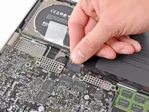
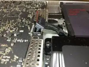
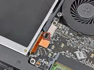
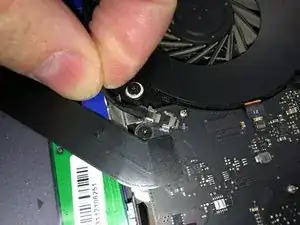
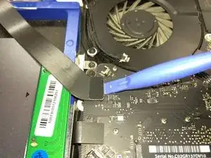
    • Before disconnecting the camera cable, a small plastic retainer stuck to the logic board must first be moved out of the way. In late-2011 models you can skip this step because there is not a plastic retainer on the camera cable connector.

    • Use the tip of a spudger to push the small plastic cable retainer away from the camera cable socket for enough clearance to remove the camera cable.

    I think I should have a photo of the plastic retainer as there may be more people like me who were afraid to take the part.

    Cassio Machado -

  5. FvUcnZ1GUpc5ZNHy
    FvUcnZ1GUpc5ZNHy
    E3YNIBmZsFcEvTCp
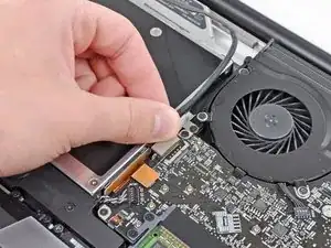
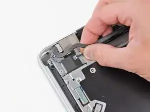
    • Pull the camera cable toward the optical drive opening to disconnect it from the logic board.

    • The camera cable socket is very fragile. Do not apply any upward force to this socket, as it may break off the logic board. Pull the camera cable parallel to the face of the logic board.

  6. OloiBStWJyZBECol
    • Carefully pull the Bluetooth cable toward the fans to disconnect it from the Bluetooth board.

    • Pull the cable parallel to the face of the optical drive.

    These pictures are not whats on my a1297. For example the Bluetooth connector is not set up like this. Its actually set up like the Late 2011 A1286. Not sure which model this is.

    Sean Love -

  7. cDoKFfgwpOGawZwT
    cDoKFfgwpOGawZwT
    MqRDAmJvhCqODnMU
    • Use the flat end of a spudger to peel the thin plastic cover off the top and sides of the Bluetooth board housing. For late-2011 models check out the other picture because the connector location is in a totally different location.

  8. uxBKVcSvyFxaTycF
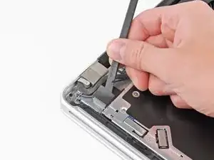
    • Use the flat end of a spudger to pry the Bluetooth antenna connector up and off its socket on the Bluetooth board.

  9. 4CKCYUt1uQeXOFUd
    4CKCYUt1uQeXOFUd
    tGYWOblbswxGbOIa
    • If present, remove the small piece of EMI foam near the Bluetooth board.

    • De-route the camera cable from the slot molded into the Bluetooth board housing.

  10. oAAyewTSJrpP2rEE
    oAAyewTSJrpP2rEE
    n56ZGAXODDYgecbO
    • Remove the two 7.1 mm Phillips screws securing the camera cable retainer to the upper case.

    • Remove the camera cable retainer from the upper case.

  11. 5pdwljZTG4iHIXvP
    5pdwljZTG4iHIXvP
    XJTfJ5V6lnBs1VY1
    cRQKslcN6BEij3ag
    • Lift the black plastic flap attached to the display data cable retainer and rotate it toward the DC-In side of the MacBook.

    • Pull the display data cable out of its socket.

    • The display data cable socket is very fragile. Do not lift the connector upward as you disconnect it, as the socket may break off the logic board. Pull the cable parallel to the face of the logic board.

  12. TlPWXHDvhxJGnL2K
    TlPWXHDvhxJGnL2K
    Kd1nAKtPI5wliOXN
    • Remove the two 7.1 mm Phillips screws securing the display data cable retainer to the upper case.

    • Remove the display data cable retainer.

  13. NSmOTCNu2OJx3DVK
    NSmOTCNu2OJx3DVK
    4X5LUDyivHT4xCVL
    • Remove the two outer 6.8 mm T6 Torx screws from each of the two display brackets (four screws total).

    • We purposely have you leave one screw attaching each display bracket to the upper case to aid in future steps.

    I viewed a YouTube video showing this process. There was a warning about the stripping of the Torx screws being common on this mid-2009 model MBP. Is that something you have come ever across? It's the only thing holding me back from attempting this myself. TY in advance!

    s0mvh -

    Taking those hinge screws out can be difficult (they are fat, and they resist turning). In my first attempt I destroyed the Torx screwdriver bit (soft metal, I discovered, so the bit twisted into a corkscrew before it snapped off). After buying the ifixit screwdriver set I found that the driver bits were tough enough, but the screws still would not budge! So, I used a small mole-grip wrench to hold the metal part of the screwdriver, and GENTLY turned until I felt the screw give way with a click. Luckily, the threads did not strip. However, if you find that even with that extra torque from the wrench, it is still resisting in a big way, go one more step and try a very tiny drop of thread-loosening fluid on it. (That last suggestion, however, is risky, so be careful.... do not let any fluid get anywhere except the screw, and then give it time to work).

    RichardL -

    What's the url to the youtube video you mentioned?

    David Fear -

    Too late. I should have read the comments first but I was rushing. I just stripped two of them. They are in there super tight.

    Sean Love -

    I just did this now (11:21 am, Sept 18 2014) A tip for removing glass bezel on the frame if you don't have a heat gun. I used a very sharp but super thin razor (the one for shaving) and slice the adhesive. Be careful not to hit the lcd. After slicing all around, get any thin plastic card and slide it all around the bezel until the glass comes off. I have a mid 09 macbook pro 17" that had a broken lcd and a 2010 macbook pro i7 17" that had a logic board problem but good lcd. Both A1297. I did it twice using my method.

    J A N Marquez -

    Thanks! This made my display so much easier ...and I just love my new ifixit toolkit. Now... what else can I fix! lol Much appreciated!

    Leshell -

    Be super careful with this part. I just stripped two of these t6 screws and have two more that will not budge. Now I have to figure out how to get them out. How did these get so tight? What a headache.

    Sean Love -

  14. dZlFLYgHJHP6gymW
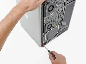
    • Open your MacBook Pro so the display is perpendicular to the upper case.

    • Place your opened MacBook Pro on a table as pictured.

    • While holding the display and upper case together with your left hand, remove the remaining T6 Torx screw from the lower display bracket.

  15. IstohD6U2OpUxFRF
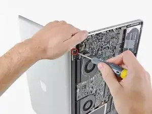
    • Be sure to hold the display and upper case together with your left hand. Failure to do so may cause the freed display/upper case to fall, potentially damaging each component.

    • Remove the last remaining T6 Torx screw securing the display to the upper case.

  16. J6IGDwtlHfiDcgEQ
    J6IGDwtlHfiDcgEQ
    AqXHJQpKskqWhGHr
    1cHntxBOPmyrjumJ
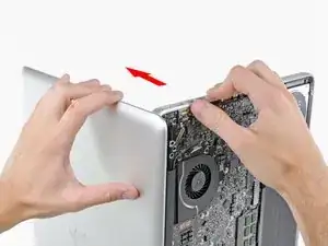
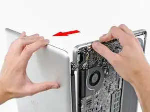
    • Grab the upper case with your right hand and rotate it slightly toward the top of the display so the upper display bracket clears the edge of the upper case.

    • Rotate the display slightly away from the upper case.

    • Lift the display up and away from the upper case, minding any brackets or cables that may get caught.

    • During reassembly, fit the display into place and install the display bracket Torx screws, then close the lid and lay the laptop upside-down to check the alignment of the screen to the body. If necessary, loosen the screws and realign the display before tightening.

  17. 3G6NBJXIGFBsGHwP
    3G6NBJXIGFBsGHwP
    4KRaFBxINmPmnGmD
    LnkBwDNXCSkchKwB
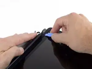
    • It's very easy for the rubber display gasket to deform when exposed to heat, so it is best to remove it before using a heat gun to remove the display glass.

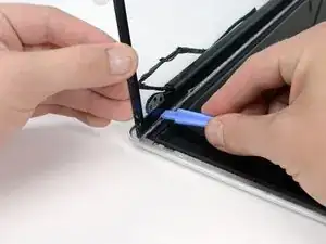
    • Insert a plastic opening tool underneath the black rubber gasket at the bottom left corner of the display assembly.

    • Gently pry the wide edge of the gasket up from the back case.

  18. nlfPlTuTHwsAPBjr
    nlfPlTuTHwsAPBjr
    QWILHvpVUdZAjO6h
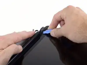
    • Starting with the freed corner, pull the left gasket off the left side of the display assembly.

  19. wiK5AccbtQkGibnL
    wiK5AccbtQkGibnL
    B1BJDGWlXBcDvexR
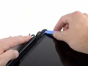
    • Continue pulling the display gasket off the display assembly across the top edge.

  20. LHaCsZtldUA2l3uL
    LHaCsZtldUA2l3uL
    YoXawND6AeTyDqMj
    MAGkImeLSM6nSKvo
    • Continue pulling the display gasket off the display assembly down the right side.

    • Pull the gasket off the bottom edge of the display to completely free it and set it aside.

  21. OBOrLtOaeU5lybgI
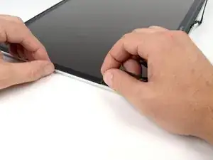
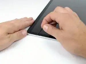
    • In the following steps, you will use a heat gun to soften the adhesive securing the outer black border around the underside of the front glass panel to the display.

    • Before starting, be sure to clean the display glass with a lint-free cloth moistened with a mild solution; it will make the suction cup adhere better, and will make checking for dust on reassembly easier.

    • With the heat gun set to low, start by heating the outer black border near the upper right corner of the glass panel.

    • Due to the heat applied, it is normal for a layer of condensation to develop on the inside of the glass panel and/or the outside of the LCD. It can be removed with glass cleaner once the glass is separated from the display.

    Problem: A model A1297 does not have the black border, it has an aluminum bezel. Wondering if it too, comes up by heat?

    buz -

    I didn’t want to wake people in the house at midnight with a heat gun so i tried something else and it worked fantastically well.

    1) i used an oil-filled electric radiator and set it to high

    2) I put a small box (about 6 x 9”) on that radiator

    3) i put the display face-down on the box ; the box deflects the heat to the edges and slowly heats the edges to a nice hot temp not too hot.

    4) I used 4 credit cards as i didn’t have guitar picks. I was able to do all four sides with one heating process.

    I was still able to touch the surface it was probably under 180° (the magic temp that virtually any electronic device can survive).

    I’ve used toaster ovens to preheat an iPad for screen removal; this works much better it only heated the edge.

    awr -

  22. C4uU4MDMFZ4ndhWT
    C4uU4MDMFZ4ndhWT
    rKQycDkbxwuPYPyf
    QrvPfBGLGvMiTeWV
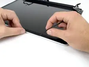
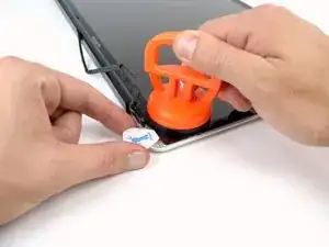
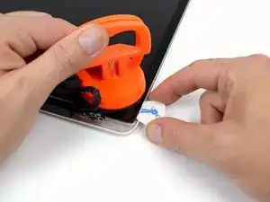
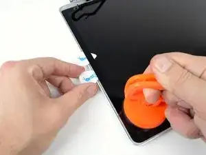
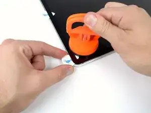
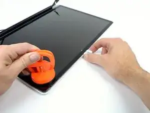
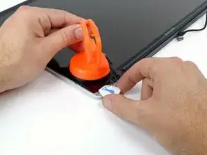
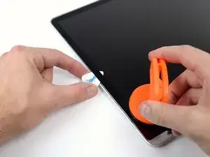
    • With the panel sufficiently heated, fasten a heavy-duty suction cup near the lower right corner of the display glass.

    • To attach the suction cups we sell, first position the suction cup with the movable handle parallel to the face of the glass panel. While lightly holding the suction cup against the glass, raise the movable handle until it is parallel with the other handle.

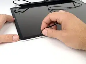
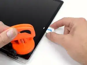
    • Gently lift the corner of the display glass enough to insert a guitar pick between it and the display assembly.

    • Use the guitar pick to gently pry up the adhesive securing the front glass to the display.

    • Pry up the glass panel along the right edge of the display up to the halfway point.

    • Leave the guitar pick in place halfway up the right side of the display and remove the suction cup.

  23. TVHdesyG2FjfjUDL
    TVHdesyG2FjfjUDL
    oDqOD1JvyyFq1RDx
    Ub5W6MvFuTHPochn
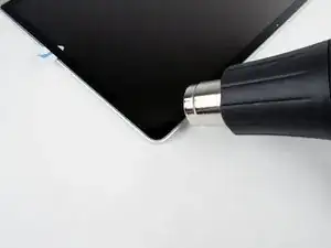
    • Use a heat gun to soften the adhesive under the display glass along the right and top edges of the display.

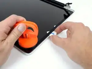
    • Attach a suction cup to the upper right corner of the front glass panel.

    • Pull up on the glass panel while you use a second guitar pick to separate it from the rest of the display assembly.

    • Continue working along the right edge of the front display glass until it is separated from the display.

  24. gQEJABYwhuSiEyCJ
    • Work along the top edge of the display assembly, carefully prying the adhesive up with the guitar pick.

    • Stop prying about an inch before you reach the iSight camera. Leave the guitar pick in place and remove the suction cup.

  25. xTogEgmkvTM4Toet
    xTogEgmkvTM4Toet
    TBVKGa4YdQ2AvCNh
    uZObn5eMhNvWrjTB
    • Repeat steps 22 through 24 for the left side and the left top edge of the display.

  26. wUJGfGsQOw6WRUOs
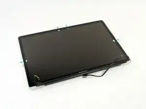
    • After prying up the three edges of the display glass, you should have four guitar picks resting underneath the panel, as shown.

  27. jdWYsWivbDLWPfud
    jdWYsWivbDLWPfud
    Qg1QTByMNcYfso15
    Ytx6dRTZF2gVVQpb
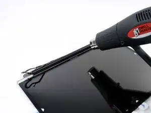
    • With the heat gun set to low, heat the bottom edge of the display to soften the adhesive holding the glass in place.

    • A number of cables and the AirPort card lie underneath the clutch cover, so do not heat the area for too long.

    • Slowly lift the top edge of the glass panel and gently rotate it out of the display.

    • If necessary, use a plastic opening tool to free any part of the lower edge of the glass that is still attached.

    • Before reassembling, be sure to clean both the inside of the glass display panel and the LCD as any dust or fingerprints trapped inside will be annoyingly visible when the machine is on.

  28. 6bJ3JDHKPCaPQ54r
    6bJ3JDHKPCaPQ54r
    4hQWlunhAkhGcuhG
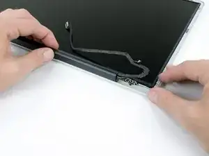
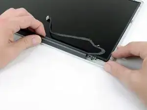
    • Holding the clutch cover firmly, slide it towards the right display hinge.

    • The clutch cover will move approximately 1 cm to the right. Do not force it pass this point.

  29. SrPkJce33kIYr1Tu
    SrPkJce33kIYr1Tu
    LBnNnd6stTIQOvdP
    • Lifting the left edge of the clutch cover, gently rock it back and forth on its long axis while pulling it away from the display.

    • Remove the clutch cover from the display, minding any cables that may get caught.

    How the he'll do I get it back on?

    liam Carroll -

    How the he'll do you get the cover back on?

    liam Carroll -

  30. iW5cVPGKtOCMTtsp
    • Remove the four 2.3 mm Phillips #00 screws securing the LCD to the rear display bezel.

  31. aJ1U423YdmxNQq1i
    aJ1U423YdmxNQq1i
    OIFwJGZGkyNAHk4Q
    WZV6YrAMhgJFERQf
    • Lift one of the top corners of the LCD panel out of the rear bezel with a plastic opening tool.

    • Grasp the top corners of the LCD and rotate it upwards, slightly out of the display.

    • Pull the LCD toward the top of the display panel, freeing the screw tabs from underneath the rear display bezel.

    When replacing the LCD not only do the screw tabs at hinge side have to slide into their slots but also LCD extends at that end into a slot leaving the groove free for the clutch cover

    osdoctor1 -

  32. t5KKLhA2VbeJp3Xr
    t5KKLhA2VbeJp3Xr
    jnQKGifYSexwYCQd
    • Carefully guide the LCD cable through the slot in the rear display bezel.

    • You may need to rotate the display slightly to get the cable through.

  33. NZPqajAOHueOUEJW
    NZPqajAOHueOUEJW
    2fU1IgcYo1IeBDhR
    • Flip the LCD over and lay it face down, being careful to not put too much stress on the display cable.

    • Peel the piece of tape covering the display data cable connector away from the edge closest to the LCD.

  34. Qgg2qkjYDbARFnHP
    Qgg2qkjYDbARFnHP
    i5ntWCQNCcPM3FPq
    • Use the tip of a spudger to flip up the thin steel retaining clip securing the display data cable to its socket on the LCD.

    • Pull the display data cable straight away from its socket on the LCD.

    • Lift the LCD out of the display assembly and set it aside.

  35. pKXkxaLOnmEH5Zdt
    • Remove the two 2.7 mm Phillips #00 screws securing the camera board to the rear display bezel.

  36. gCi6i5QgSF3gMqSx
    • Lift and remove the camera assembly out of the rear display bezel.

  37. enmG1gVRGYOUMtUQ
    • Pull the camera/AirPort cable straight out of its socket on the camera board.

  38. LjRq4ONS1ut123SO
    • Remove the 2.7 mm Phillips #00 screw securing the AirPort board bracket to the rear display bezel.

  39. U6hfyyNSCRXIGfwM
    U6hfyyNSCRXIGfwM
    PdIMiRVoBANBcOKV
    • Move the AirPort board bracket towards the bottom of the display case with the tip of a spudger so that it does not block the AirPort board cable.

    • Use the tip of a spudger to disconnect the AirPort board cable by rocking it back and forth until it is free.

  40. FJEXQrwhBw535xFD
    • Once the cable is disconnected, remove the plastic bracket from the rear display bezel.

  41. 64DFTNrAXfiyLhFX
    • Remove the single 1.9 mm Phillips #00 camera cable screw.

  42. vALqwA4L5YyQIvG1
    vALqwA4L5YyQIvG1
    CKHO5xrygiAwx5Ud
    • De-route the camera/AirPort cable from the display housing.

    • Carefully pull the camera/AirPort cable through the slot in the aluminum housing underneath the right display hinge.

Abschluss

To reassemble your device, follow these instructions in reverse order.

Brett Hartt

Mitglied seit: 13/04/10

125814 Reputation

Ein Kommentar

Hi :-)

is there a way to get this cable? I have a 17" mbp mid-2009 and i want to fix this cable.

thanks for the answers.
Henri LARGET -