Einleitung

  1. kCVQRtqeAZMJyO5B
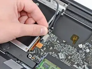
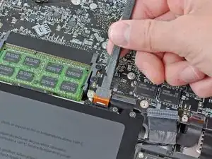
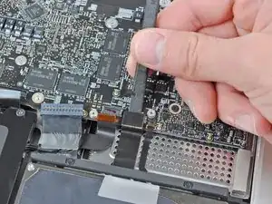
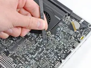
    • Hebe den Stecker des linken Lüfters mit dem Spudger aus seinem Anschluss auf dem Logic Board heraus.

    • Der Steckers lässt sich leichter lösen, wenn du den Spudger der Länge nach unter den Lüfterkabeln verdrehst.

    On my 2011 MBP, the wiring is twisted a half turn. Its not possible to insert the connector the wrong way around, but it just seems sloppy that it was designed to require stressing the wire this way.

    anon -

  2. 2LPUZWSpgGvmKpau
    2LPUZWSpgGvmKpau
    DEvSWADaygxU5AM5
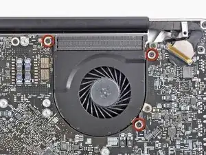
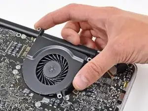
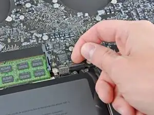
    • Entferne die drei 3,1 mm Kreuzschlitzschrauben, mit denen der linke Lüfter am Logic Board befestigt ist.

    • Entferne den linken Lüfter vom oberen Gehäuse, achte dabei darauf, dass sich keine Kabel verfangen.

    on my early-2011, these screws were Torx

    Segue -

  3. lIq1IJfXiyHdUZEa
    lIq1IJfXiyHdUZEa
    GkIDSmIcKMt2vAok
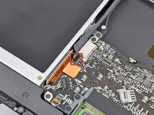
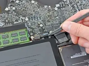
    • Klappe den Sicherungsbügel am Flachbandkabel der Tastaturbeleuchtung mit dem Spudger oder dem Fingernagel hoch.

    • Achte darauf, dass du nur am Sicherungsbügel hebelst, nicht am Anschluss selbst.

    • Ziehe das Flachbandkabel der Tastaturbeleuchtung aus seinem Anschluss heraus.

    “Pull” ??? Don’t you mean to say “slide horizontally towards the gap where the fan was?”

    anon -

    On my early 2011 Macbook Pro unibody 17” - there is another small cable to disconnect between this, the keyboard backlight ribbon cable and the optical drive cable. Not sure what it’s for, but thought to mention is. It is small metal plug and socket and says “AC” on it.

    Cyrus Buckley -

    I managed to pull the tiny retaining flap off of the socket entirely, then lost it… Not to worry, the ribbon cable sits securely in the socket even without the flap, and the keyboard backlight functions perfectly after reassembling the laptop

    D K -

    slide/wiggle gently parallel to the board - mine was sticky

    Andrew A -

  4. vjAjiYAhKNfjaynm
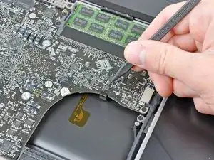
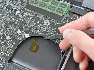
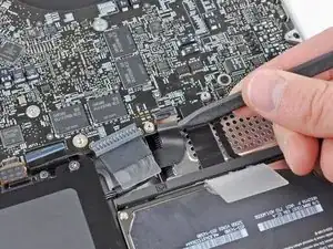
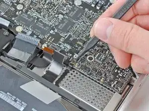
    • Bevor du das Kamerakabel ablösen kannst, musst du erst eine kleine Kunstoffhalterung, die am Logic Board festgeklebt ist, aus dem Weg schieben.

    • Drücke die kleine Kunstoffkabelhalterung mit der Spudgerspitze vom Anschluss des Kamerakabels weg, so dass genug Platz zum Ausbau des Kamerakabels entsteht.

    exactly HOW do you remove it? pull up? slide horizontally?

    anon -

    On my late (?) 2011 MBP, this connector is very tiny, and the cable covers the screw holding the optical drive.

    The connector has two tiny metal tabs. Use your fingernails to slide it backwards horizontally towards the optical drive.

    anon -

    Bit of a levering horizontally. Remove the carbon fibre patterned tape off the top of the connector to expose the connector then slide (break the adhesive bond) on the small oblong black plastic passed, towards the optical drive module. The connector can then be disengaged. It's quite difficult to unlatch the connector! Take extreme care

    Paul Buckingham -

    not on my 17” late 2011

    kenneth krabat -

    On my late 2011 MBP there are two connectors at this place: One big connector like the silver one shown on the fotos (but in my case it is black), and the tiny one as discribed in the comment from anon 10/14/2017). In contrast to the fotos, this tiny connector is on the opposite side of the big one, on the edge close to the right fan. To disconnect this connector, follow the instructions from anon 10/14/2017.

    The cable going to the big connector is in my case a wide black ribbon cable running diagonically over the optical drive. To remove the connector of this cable from the socket, pry it upwards carefully with your fingernails or a spudger.

    Sebastian Plickert -

  5. GxwMDqToVAjYVCbt
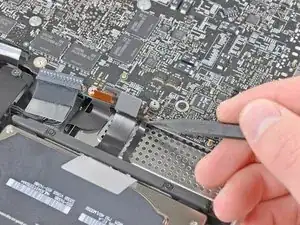
    • Ziehe das Kamerakabel zur Öffnung des optischen Laufwerks hin und trenne es vom Logic Board ab.

    • Der Anschluss des Kamerakabels ist sehr empfindlich. Ziehe an diesem Anschluss niemals nach oben, er kann aus dem Logic Board herausbrechen. Ziehe das Kamerakabel parallel zur Oberfläche des Logic Boards.

    This step and the previous one (plastic retainer) were very different on my logic board. It's an early 2011, 17" that I bought second hand. I'm wondering if the logic board was previously replaced.

    Leo Magellan -

  6. QLSEtQN4nHXlKiWO
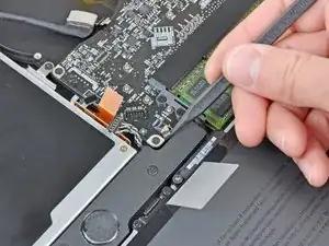
    • Heble den Stecker des optischen Laufwerks mit dem flachen Ende des Spudgers aus seinem Anschluss auf dem Logic Board hoch.

  7. jVdEHamgG36mTRKu
    • Heble den Stecker des Tieftöners und des rechten Lautsprechers mit dem flachen Ende des Spudgers aus seinem Anschluss auf dem Logic Board hoch.

    • Heble unterhalb der Kabel.

    how do you reconnect this?

    jcatron3 -

  8. lFNrWxsJfAZW6hkk
    lFNrWxsJfAZW6hkk
    rBUEYfwgULQjHpLV
    • Klappe mit dem Fingernagel oder der Spudgerspitze den Sicherungsbügel am Anschluss des Infrarotsensor-Flachbandkabels hoch.

    • Achte darauf, dass du nur am Sicherungsbügel hebelst, nicht am Anschluss.

    • Ziehe das Infrarotsensor-Flachbandkabel aus seinem Anschluss heraus.

    The IR sensor cable also connects the Hall Effect switch that detects whether the lid is closed or open (and thus shuts off the display, puts the computer to sleep, wakes it up, etc.) to the logic board.

    How do I know? I re-pasted my late 2011 17" MBP and forgot to reconnect it. The machine would not sleep automatically when the lid was closed anymore. Re-connecting the cable fixed it.

    Kevin -

    thanks for the info !!!! i got the same problem with sleep because the cable was not properly connected

    Chin Soon Cheong -

  9. W36qeOfglMXgRUKD
    W36qeOfglMXgRUKD
    2SZsOwskBZy2ist6
    ufIVbTro1YBE6KH3
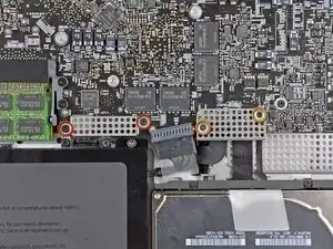
    • Entferne folgende vier Schrauben:

    • Zwei 3,5 mm Kreuzschlitzchrauben

    • Beim Modell von Anfang 2011 können das auch Torx T5 Schrauben sein.

    • Zwei 1,6 mm Kreuzschlitzschrauben

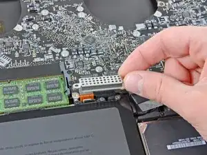
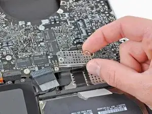
    • Entferne die beiden Steckerabschirmungen vom Logic Board.

    On my early 2011 laptop, the screws on the left hand shield were T6 screws. The others were Phillips head.

    Mark Morgan -

    The same applies to the late 2011 model.

    Sebastian Plickert -

  10. e6DCLBs4nCaelVAH
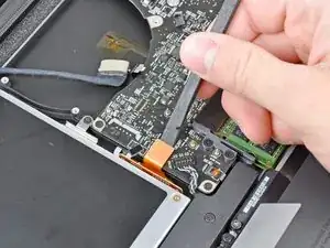
    • Heble den Trackpadstecker mit dem flachen Ende des Spudgers aus seinem Anschluss auf dem Logic Board hoch.

  11. dpQSIwK5PEVxx2YK
    dpQSIwK5PEVxx2YK
    ojvtIVOPmZLRgfAD
    • Klappe mit dem Fingernagel den Sicherungsbügel am Anschluss des Tastatur-Flachbandkabels hoch.

    • Achte darauf, dass du nur am Sicherungsbügel hebelst, nicht am Anschluss.

    • Ziehe das Tastatur-Flachbandkabel aus seinem Anschluss heraus.

    • Beim Einbau ist es sehr praktisch, wenn du ein kleines Stück Klebeband als Handgriff auf das Tastatur-Flachbandkabel klebst (die Kontakte müssen aber frei bleiben). Richte das Kabel am Anschluss aus und ziehe es behutsam hinein, bis es richtig sitzt.

    Thanks for the great guide!

    Tip for re-seating the keyboard cable: put a piece of sticky tape on, fold over at the top end, re-seat the connector (carefully!) with a spudger and (gently!) pull the tape 'over' the connector on the logic board until you feel it nudges in fully. Notice the emphasis on "carefully" and "gently"... :)

    LeonSteyns -

    Thanks for this manual! I used it to replace the keyboard. I would not recommend it as an easy job and it is not described on Ifixit for unknown reasons. But I did it and everytinhg worked fine. 2 remarks about the conncetion for the keyboard. In my Macbook 17 Pro (mid 2009) there is a litlle lever that clamps the keyboard 'cable'. You can get it out easily (I did that too because I did not see it then), but to reassemble it it is better to uplift the little lever and then move the 'cable' in with sticky tape (thanks for that tip!)

    I had to redo it 3 times to get it working. With the lever up and then clamping the 'cable' by pushing it down it worked AND it solved the power button problem. Please be carefull as said in the manual, it is all very delicate!

    And for replacing the keyboard; prepare yourself for a lot of tiny screws! (some of them are stuck and had to be removed with force, be warned!)

    Another tip

    Edlef Heeling -

  12. QAalm6MoyjLpNX4T
    QAalm6MoyjLpNX4T
    QJYICCKI2LeoVT3F
    • Klappe mit dem Fingernagel den Sicherungsbügel am Anschluss des Flachbandkabels des Expresskartengehäuses hoch.

    • Achte darauf, dass du nur am Sicherungsbügel hebelst, nicht am Anschluss selbst.

    • Ziehe das Flachbandkabel des Expresskartengehäuses aus seinem Anschluss heraus.

    It might be easier to remove the ExpressCard ribbon cable in Step 18 by removing the Hard Drive cable first...use your judgment.

    David DeAnda -

  13. 1vpntjDTIorkmNUt
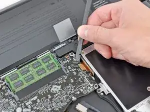
    • Hebe den Festplattenkabelstecker mit dem flachen Ende des Spudgers aus seinem Anschluss auf dem Logic Board hoch.

  14. OwH1gf21Lim6UOOY
    OwH1gf21Lim6UOOY
    WqFTqsjUbG4ddKyJ
    • Klappe mit dem Fingernagel den Sicherungsbügel am Anschluss des Akkuladeanzeige-Flachbandkabels hoch.

    • Achte darauf, dass du nur am Sicherungsbügel hebelst, nicht am Anschluss selbst.

    • Ziehe das Akkuladeanzeige-Flachbandkabel aus seinem Anschluss heraus.

    When reassembling, slide the ribbon cable underneath the connector then lock it into place.

    Phil Melendez -

  15. pFZkgKwjGMIGWSNo
    pFZkgKwjGMIGWSNo
    1uSC4uTK1pucOHaj
    KDi5kIcOeAQ5WUqH
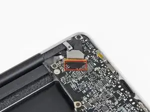
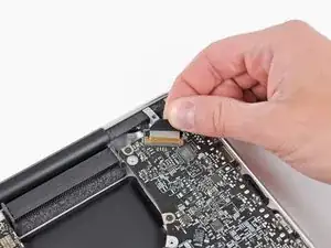
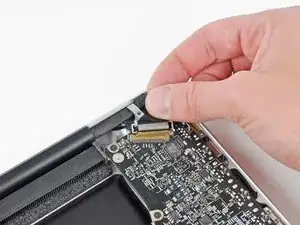
    • Hebe die Kunstoffklappe am Halter des Displaydatenkabels an und drehe sie zur Seite mit der Ladebuchse hin.

    • Ziehe das Displaydatenkabel aus seinem Anschluss heraus.

    • Der Anschluss des Displaydatenkabels ist sehr empfindlich. Hebe den Stecker beim Ablösen nicht nach oben, der Anschluss könnte sonst aus dem Logic Board herausbrechen. Ziehe das Kabel parallel zur Oberfläche des Logic Boards.

    Be SUPER EXTRA CAREFUL when connecting this cable back!!! Use a magnifying glass or headset to see what you are doing.

    When I plugged it in the first time (finished the rest of the process and restarted the mac) I got green lines all over my screen…

    I replugged it a total of 4 times to get it right even cleaned it with alcohol. Now everything is working, but I freaked out a bit :)

    Tom -

    I would describe the removal as “sliding back towards the corner". “Pulling out", to me, implies pulling up away from the board.

    MaFt Morley -

    When reassembling, slide the cable underneath the connector. It doesn’t snap on.

    Phil Melendez -

    This is the trickiest step in this whole process, both detaching and reattaching. I’ve been through this logic board repair scenario with my Early 2011 about 4x now, and if, when you reassemble, you’re still having problems with your display of any sort, this is your number 1 achilles heel is this connector getting dirty (use high purity over 90% isopropyl alcohol often found at drug stores next to the regular 70% stuff for cleaning) or not seating properly. I have broken off the connector bracket mount that goes over the top but was able to use pure silicone to safely reattach it. Don’t break that top bracket off sliding this puppy out; it’s a very dicey situation!

    Segue -

    I had no idea what "toward the DC-in side" meant. "DC-in" refers to the Magsafe connector/port in the corner of the machine (upper right when the machine is facedown with lower case removed).

    The plastic flap and its little metal bracket broke off from the cable when I tried to rotate it out of the socket. Will this cause problems? I'm assuming it was just a handle. I was successfully able to slide the cable out, and then back into the socket on reassembly, even after the bracket/tab broke off.

    Leo Magellan -

  16. QCH3KIs6TZQoAbTN
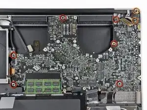
    • Entferne folgende acht Schrauben, mit denen das Logic Board und die Versorgungsplatine (DC-In Board) am oberen Gehäuse befestigt sind:

    • Sechs 3,2 mm Kreuzschlitzschrauben

    • Am Modell von Anfang 2011 können dies auch Torx T6 Schrauben sein.

    • Zwei 7,6 mm Kreuzschlitzschrauben

    The Six 3.2mm screws can in some cases be torx instead of phillips

    Finntastic -

    I've got a great idea for keeping the tiny screws safe and also labelled up e.g. these 6+2 screws belong to the logic board - simply use 'Post-It' sticky note upside down on your desk and use the sticky bit to keep the screws from rolling around getting themselves lost :-)

    Paul Reddington -

  17. P6pZ3XnSOGH6sGIQ
    P6pZ3XnSOGH6sGIQ
    xury3LuSZ4kTJEPO
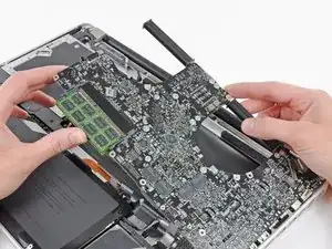
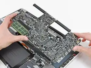
    • Fasse die Logic Board-Einheit nur an den Kanten an.

    • Hebe die Logic Board-Einheit an der Seite nahe am optischen Laufwerk an und hebe sie vom oberen Gehäuse weg.

    • Achte darauf, dass du das Logic Board und die Versorgungsplatine (DC-In Board) gleichzeitig entfernst.

    • Ziehe die Anschlüsse und die Versorgungsplatine (DC-In Board) von der Seite des oberen Gehäuses weg und entferne die Logic Board Einheit, achte dabei darauf, dass sich keine Kabel verfangen.

    When lifting the logic board be careful! The rubber foam around the microphone may have adhered the microphone to the uppercases grill work so as you lift you could rip the connector from the ribbon cable.

    * Take a small spatula and thought the fan opening carefully dislodge the microphone from the grill as you lift the logic board.

    * To locate the microphone note on the next slide the small unit between the fingers of the hands.

    Dan -

    You need to remove the Phillips screws near the optical drive. I don’t see that in the instructions anywhere.

    David -

    Attach the DC connector with screws first when reassembling.

    Phil Melendez -

Abschluss

Um dein Gerät wieder zusammenbauen, folge den Schritten in umgekehrter Reihenfolge.
Andrew Bookholt

578335 Reputation

0 Kommentare