Einleitung

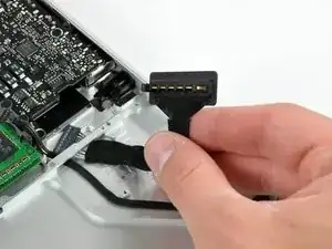
Über diesen Anschluss wird der Akku geladen und mit dem Logic Board verbunden.

  1. qPsGdXwUZZBT6RJa
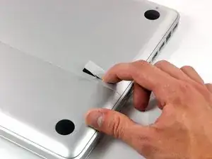
    • Lege die Oberseite des Gehäuses mit geschlossener Klappe auf eine glatte Oberfläche.

    • Drücke den Verschlusshebel auf der geriffelten Seite der Klappe in das Gehäuse des MacBooks, bis du den Verschlusshebel auf der anderen Seite greifen kannst.

    • Öffne den Verschlusshebel so weit, dass er senkrecht steht.

    This is not a a1278 unibody MacBook Pro. A1278 MacBooks backs are one solid metal piece not two separate pieces. This guide is for a different MacBook Pro.

    Brad Burgeson -

    This guide isn’t for a pro; it’s a MacBook unibody.

    Nicholas -

    So, it turns out that Apple used the model code A1278 for quite a few different Mac models, including both Pro and non-Pro versions! This guide is for the non-Pro Macbooks. There’s also one for the Pro models with the same A1278 identifier.

    tempelmann -

  2. Pf4wGUpXWyJ3tAfH
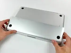
    • Die Bodenklappe sollte nun ein kleines Stück offen stehen.

    • Die Klappe kann nun nach oben aus dem Gehäuse des MacBooks genommen werden.

  3. WkwQip2DfR1iJLMX
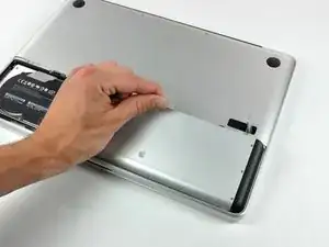
    • Versichere dich, dass sich die Entriegelung der Klappe in senkrechter Position befindet, bevor du weitermachst.

    • Ziehe an der weißen Plastiklasche und damit den Akku gerade nach oben und aus dem Laptop.

    Great tutorial ! great step !

    Leo Etcheverry -

    Even though it’s specifically stated, you have to make sure the access door latch is vertical or the battery won’t be removable.

    Henry Kim -

  4. mgYUuNTR1BjI1A6i
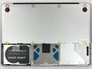
    • Entferne die im Bild gezeigten acht Schrauben, die die Bodenplatte mit dem Rest des Gehäuses verbinden:

    • Eine 3 mm Kreuzschlitzschraube.

    • Drei 13,5 mm Kreuzschlitzschrauben.

    • Vier 3,5 mm Kreuzschlitzschrauben.

    On my model, it seemed the top-left was 3.5mm and the bottom 4 were 3 mm.

    Jim -

    Make sure you have a good quality Phillips screwdriver. Mine had removable tips and had a small play at the connection. As a result I didn't have a good feel and damaged my screws (those securing the fan and the top left in step 23). Game over for me installing new thermal paste...

    Be very carefull with your screws! Especially those on the inside.

    Nickolas Michelinakis -

    You can get away with a Phillips #00 for many of the screws involved but the 4 at the bottom case split are likely to strip if you don’t use a JIS #00 or, in a pinch, a Phillips #000.

    Bill Cole -

    I used the Phillips #00 tip from my Pro Tech Toolkit, and it worked well enough. But yes, maybe #000 might have been better on the lower row of screws. Note to myself: Always read the comments first.

    Les Kitchen -

    When replacing these screws, the order to replace them in is as follows:

    1, Top left

    2. Top right

    3. Top center-left

    4. Top center-right

    5. Bottom center-right

    6. Bottom center-left

    7. Bottom right

    8. Bottom left

    I hope this information is helpful.

    facebook -

    I followed my usual process of putting in all the screws loosely, then tightening them gradually in distributed pattern, to help ensure that the panel settles in place evenly. But maybe some orders are better.

    Les Kitchen -

  5. EZrPgfOVIaaIsXLR
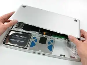
    • Hebe die Bodenplatte mit beiden Händen an und entferne sie vom oberen Gehäuse.

    Thanks for the guide!

    It's implicit in the two photos, but worth mentioning because it blocked my progress in this step for a bit: You have to put the release latch back into its horizontal, closed position before you can lift off the lower-case panel.

    Les Kitchen -

  6. ZDpbs3QyQKNgqvSk
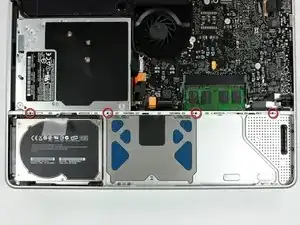
    • Entferne die vier 10,3 mm Kreuzschlitzschrauben, die die Trennwand im Gerät befestigen.

  7. LV5xyFVvTgPeeFXR
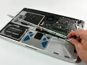
    • Hebe die Trennwand aus dem Gehäuse.

  8. kEShtwFtxA5NAUIl
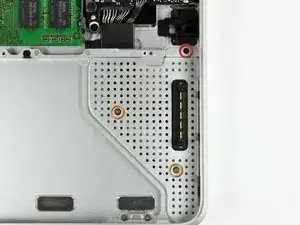
    • Entferne folgende Schrauben, mit denen die Abdeckung des Akkuanschlusses am oberen Gehäuse befestigt ist:

    • Eine 2,5 mm Kreuzschlitzschraube

    • Zwei 1,5 mm Kreuzschlitzschrauben

  9. ZCMhOBKhLcKWpgN4
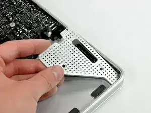
    • Hebe die Abdecḱung des Akkuanschlusses aus dem oberen Gehäuse heraus.

  10. JTCXKoYjOA5PcHoR
    JTCXKoYjOA5PcHoR
    4A1ND2jPVyc5fndx
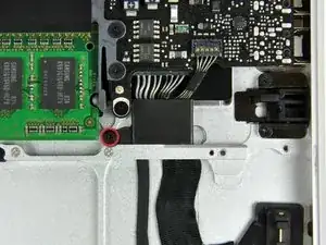
    • Entferne die einzelne 2,7 mm Kreuzschlitzschraube, mit der die Abdeckung des Akkukabels am oberen Gehäuse befestigt ist.

    • Hebe die Abdeckung des Akkukabels aus dem oberen Gehäuse heraus.

  11. 6MngWUoyfCZYqffO
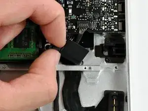
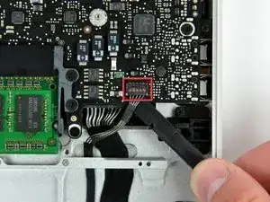
    • Heble den Stecker am Kabel der Akkuanzeige mit einem Spudger gerade vom Logic Board weg.

    Do you have a replacement part for the battery indicator cable for this model?

    Rob Bonner -

  12. umgWORWxxT6Rbnxj
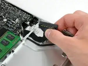
    • Löse das Akkuanschlusskabel aus der Klebeverbindung zum oberen Gehäuse ab.

  13. ELmVAZY1cUPkCm2r
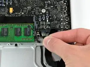
    • Ziehe das Akkuanschlusskabel ein wenig in Richtung des Logic Boards, so dass es genug Spiel hat, um mit den Fingern gefasst zu werden.

    • Löse das Kabel ab, indem du es gerade vom Logic Board weg ziehst.

  14. V33QGPJlSUFnwWPL
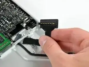
    • Fädle das Akkuanschlusskabel durch die Öffnung im oberen Gehäuse und entferne es vom Computer.

Abschluss

Um dein Gerät wieder zusammenzusetzen, folge den Schritten in umgekehrter Reihenfolge.

Walter Galan

685540 Reputation

Ein Kommentar

When reinstalling the battery connector/cable, placement of the connector is critical. If the connector isn't positioned accurately, contact with the battery terminals won't be completed. The battery connector cover will help you align the connector, but there will still be a little leeway as you screw the cover down. Position the battery first, to adjust the connector's position; then remove the battery and tighten the cover screws down. You may even want to try plugging the computer into the AC charger before completing the cover attachment, to ensure that battery is charging and the connector is correctly positioned.

adlerpe -