Werkzeuge
Ersatzteile
-
-
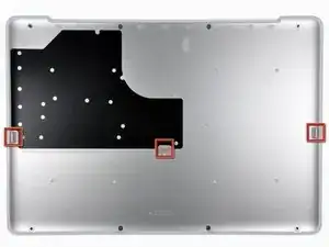
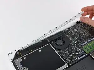
Slightly lift the lower case near the vent opening.
-
Continue running your fingers between the lower and upper cases until the upper case pops off its retaining clips.
-
-
-
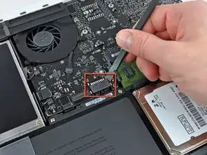
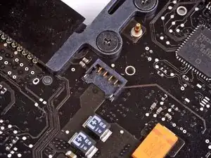
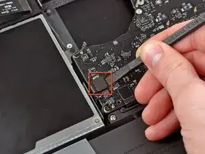
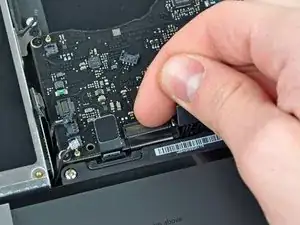
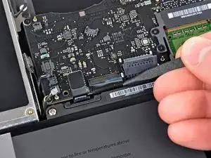
Use the flat end of a spudger to lift the battery connector up out of its socket on the logic board.
-
-
-
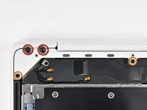
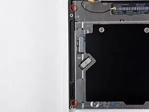
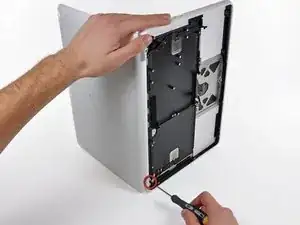
Remove the following screws from the optical drive side of the rear vent:
-
Two 10 mm T8 Torx
-
Two 5.2 mm Phillips
-
-
-
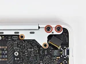
Remove the following screws from the port side of rear vent:
-
Two 10 mm T8 Torx
-
Two 5.2 mm Phillips
-
-
-
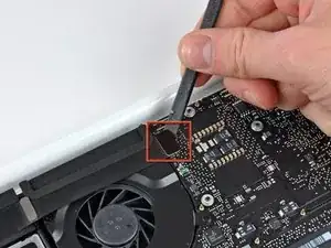
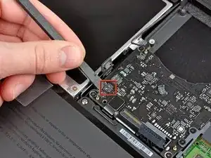
Use the flat end of a spudger to pry the AirPort/Bluetooth ribbon cable up off the logic board.
-
-
-
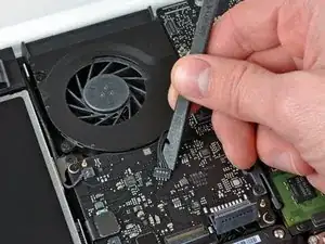
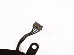
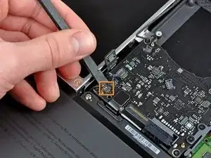
Use a spudger to pry the fan connector straight up and out of its socket on the logic board.
-
-
-
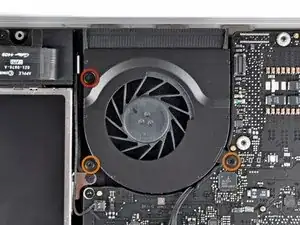
Remove the following three screws securing the fan to the upper case:
-
One 7.1 mm Phillips screw.
-
Two 5 mm Phillips screws.
-
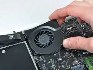
Lift the fan out of the upper case.
-
-
-
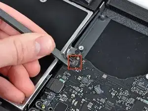
Carefully pry the delicate rear speaker connector up off the logic board. These small L/R speaker connectors are quite easily broken.
-
-
-
Use a spudger to pry the right speaker connector and sleep LED connector up off the logic board.
-
-
-
Use the flat end of a spudger to pry the trackpad ribbon cable connector up off the logic board.
-
-
-
Use your fingernail to flip up the locking flap on the ZIF socket for the keyboard ribbon cable.
-
Use the tip of a spudger to slide the keyboard ribbon cable out of its socket.
-
-
-
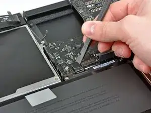
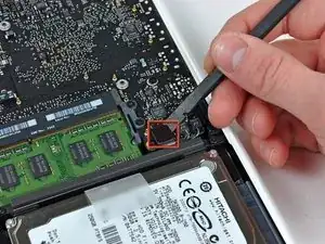
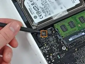
Use the flat end of a spudger to pry the hard drive cable connector up off the logic board.
-
-
-
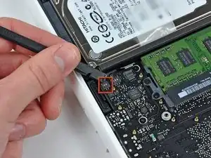
Use a spudger to pry the left speaker connector and microphone connector up off the logic board.
-
-
-
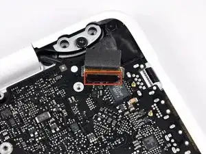
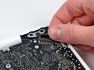
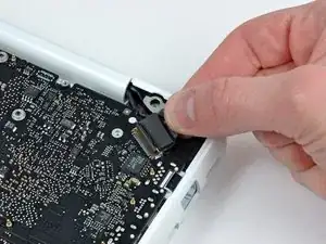
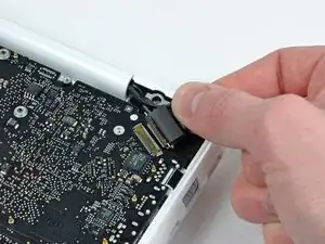
Grab the plastic pull tab secured to the display data cable lock and rotate it toward the DC-In side of the computer.
-
-
-
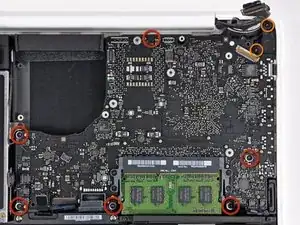
Remove the six 4.1 to 4.4 mm T6 Torx screws securing the logic board to the upper case.
-
Remove the two 4.1 to 4.5 mm T6 Torx screws securing the MagSafe board to the upper case.
-
On some models, these screws may be T7. Be careful not to strip away the head with a smaller bit.
-
-
-
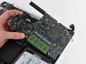
Lift the side of the logic board opposite the ports out of the upper case.
-
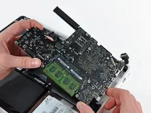
Rotate the logic board away from the upper case until the ports clear the lip molded in the upper case.
-
Pull the logic board and MagSafe board away from the edge of the upper case as one piece.
-
-
-
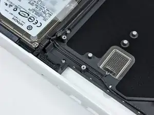
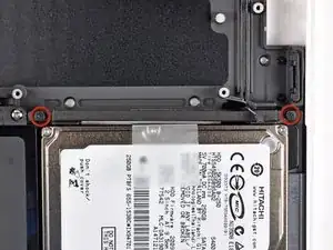
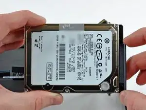
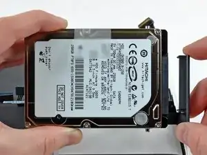
Remove the two Phillips screws securing the hard drive bracket to the upper case.
-
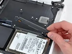
Remove the hard drive bracket from the upper case.
-
-
-
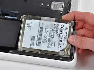
Disconnect the hard drive by pulling the hard drive cable connector away from its socket on the hard drive.
-
-
-
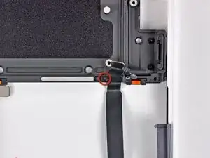
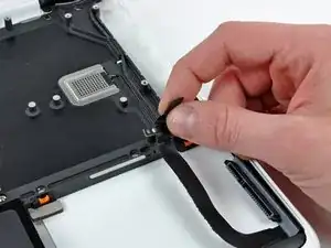
Remove the single 3.1 mm Phillips screw securing the hard drive cable to the upper case.
-
Lift the hard drive cable out of the upper case.
-
-
-
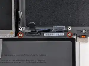
Remove two 5 mm Tri-Wing screws securing the battery to the upper case near the battery connector.
-
-
-
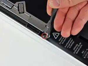
Use the tip of a spudger to carefully peel back the finger of the warning label to reveal a hidden Tri-Wing screw.
-
Remove the 5 mm Tri-Wing screw securing the battery to the upper case.
-
-
-
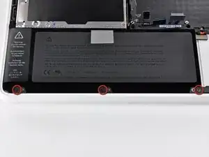
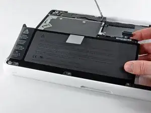
Remove three 3.1 mm Phillips screws securing the battery near the edge of the upper case.
-
-
-
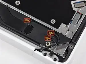
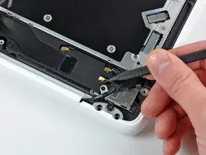
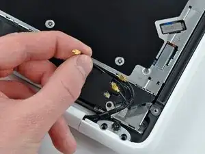
Use the tip of a spudger to pry the AirPort/Bluetooth antenna connectors (three total) up off the AirPort/Bluetooth board.
-
If necessary, de-route the long antenna cable from its slot in the rear speaker housing.
-
-
-
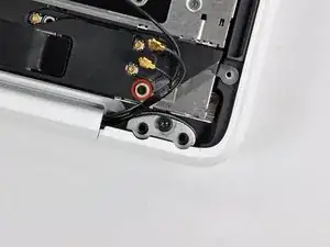
Remove the single 3 mm Phillips screw securing the antenna ground straps to the rear speaker housing.
-
-
-
Remove the single 2.2 mm Phillips screw inserted horizontally into the side of the optical drive.
-
-
-
Remove the single 4.5 mm Phillips screw securing the inner edge of the optical drive to the upper case.
-
-
-
Remove the two 2.5 mm Phillips screws securing the optical drive to the upper case near the optical drive opening.
-
-
-
Lift the optical drive near its connector and pull it away from the upper case to remove it from the computer.
-
-
-
Open your MacBook so the display is perpendicular to the upper case.
-
Place your opened MacBook on a table as pictured.
-
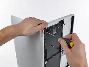
While holding the display and upper case together with your left hand, remove the remaining T8 Torx screw from the lower display bracket.
-
Before retightening the T8 Torx screws, close the display and adjust it so that the back edges of the upper case and display are aligned and the gaps at the ends of the hinge are equal.
-
-
-
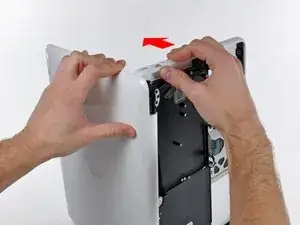
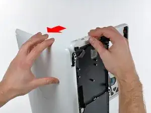
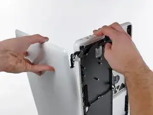
Grab the upper case with your right hand and rotate it slightly toward the top of the display so the upper display bracket clears the edge of the upper case.
-
Rotate the display slightly away from the upper case.
-
-
-
Lift the display up and away from the upper case, minding any brackets or cables that may get caught.
-
-
-
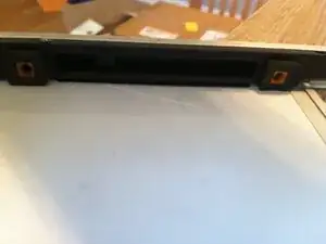
There are four orange and black rubber inserts that the hard drive sits in. One side has full circles and the other side has half circles. (The other side of the half circles are located on the hard drive bracket that was previously removed).
-
The new upper case may not have these inserts. Be sure to remove them from the old and insert into the new.
-
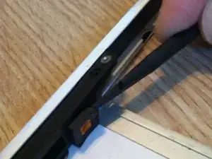
The inserts are easily pried out with a spudger or a flat tipped screwdriver. They are not glued in, but instead have notched sides to hold them in place.
-
-
-
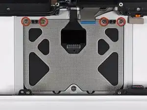
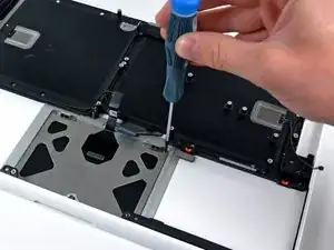
Remove the four 1.3 mm Phillips screws securing the upper edge of the trackpad to the upper case.
-
-
-
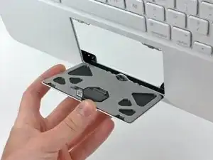
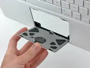
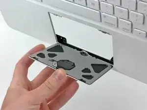
Carefully tilt the trackpad away from the keyboard side of the upper case.
-
Pull the trackpad away from its opening in the upper case to clear the two mounting tabs on its lower edge.
-
-
-
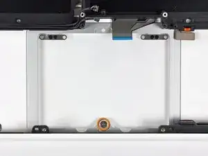
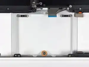
Reinstall the T6 Torx set screw until it is flush with the aluminum bracket surrounding the trackpad.
-
Place the trackpad back into its void in the upper case, being sure the lower tabs are inserted underneath the keyboard side of the upper case.
-
-
-
Reinstall the four silver Phillips screws securing the trackpad to its steel brackets.
-
Loosen all four silver screws about 1/16th of a turn.
-
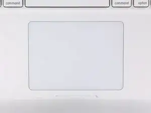
Flip the upper case over and adjust the position of the trackpad until the gap between the trackpad and the upper case is evenly spaced around the perimeter of the trackpad.
-
Tighten the four silver screws to hold the trackpad in place.
-
-
-
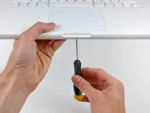
While repeatedly pressing the trackpad to simulate clicking, tighten the T6 Torx set screw until the trackpad no longer wiggles freely.
-
To reassemble your device, follow these instructions in reverse order.
24 Kommentare
NOTE: Ensure you don't pull the entire assembly straight up or the base will come off the logic board. Use an extremely small straight blade screw drive to gently loosen the inside assembly while gently pulling on the wire bundle! Will save buying a new logic board!!!!
janesem -
Some of the screws are extremely tight, I stripped at least 6 Phillips screws during the upper case replacement.
firstn10 -
I used the iFixit 54 bit kit and found that the Phillips 000 bit fits the screws better than the recommended 00 bit. When loosening or tightening I use plenty of downward pressure to keep the bit from rising out of the screw head and damaging it. The torx screws are so much easier to work with and I wonder why they don't use only those.
Definitely only use unworn, appropriately sized drivers when going into any Mac or iPhone. If the driver starts to slip, stop and access the situation. That said, I have encountered many screws with damaged screw heads. I usually first try the “rubber band” trick to loosen the ruined screw. If that doesn’t work, I often resort to using a dremel tool to cut a slot in the screw (while protecting everything from the debris generated). In all cases, be careful - one slip can do a lot of damage.
Lance J -
Great guide! My only comment would be to remove the battery first. It makes dealing with the keyboard ZIF cable much easier to install/remove.
sales -
I like that idea. I did feel challenged by the tight space when trying to put it back in it's socket.
Similarly, re-installing the logic board before the battery is helpful, as it reduces the amount of cable interference.
Lance J -
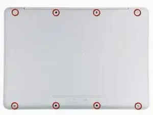
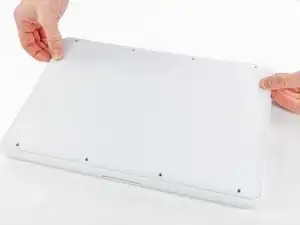
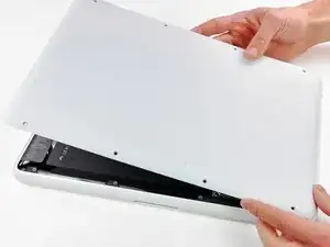
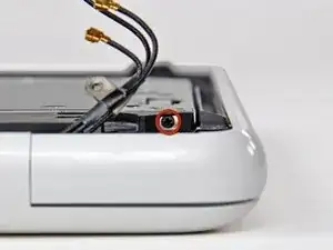
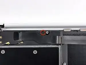
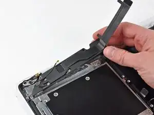
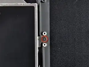



According to this page http://support.apple.com/kb/HT1651?viewl..., the 8 screws are not identical.
Can anybody tell me where each kind of screw is supposed to go?
Gregoire -
They are all 100% Identical. You were probably looking at a different model, or Apple has entered the wrong information... Hey, It happens...
weeowey weeowey -
The screws on the Late 2009 are identical. The blue lock compound might make tightening some require a little more effort.
svenaustx -
Can I replace it with a SATA 3 cable?
nm -
A1342 macbook does not have the right controller to support sata III
weeowey weeowey -
hi, i just got back from the apple store and they are really keen for me to upgrade to a new laptop since my battery is old and the screen is cracked, so glad i found ifixit i would love to upgrade this puppy! gonna make it a real sleeper! styler hall wrote about sticking 16 gb of ram in his a 1342 ? is this a simply mather of ordering 3 4gb sticks ?aslo i currently have 4 gb and would like to upgrade to 8 ( or indeed 16) does that mean i need to buy all new sticks or can i continue to use the old one and stick a new one next to it ?
thanks again mick van aar, perth western aus.
michelvanaar -
The A1342 will take up to 16 GB of RAM, however, there are only two RAM slots, so use two 8-GB RAM modules. Other World Computing (OWC) is a great reference source for info on exactly which RAM to use with which model; prices are usually much better on EBay though. Add an SSD from OWC and your machine will really scream!
I hope that helps!
gdesbrisay -
Gregoire is right. The 8 screws are absolutely NOT identical, I’m looking at them right now, weeowey weeowey.
John Guzman -
I just wanted to say that, in 2020, i used these instructions to replace the magsafe socket on my A1286, mid-2012, pre-Retina MacBook Pro. The internal layout is not quite the same but close enough for me to do the job. I skipped the steps of fully disconnecting the fans and speakers because of what others had said about breaking the sockets. it just meant I had to be extremely careful when lifting up the main board so that I did not tear and break the connections. I was able to disconnect the old magsafe socket with the board flat and in situ, but there was no where near enough room to be able to aline and press home the new par home. Reluctantly i had to lever up the board. This was difficult as there is a tapped post that holds a screw in the way close to where the USB sockets are, that prevented the board lifting up and out. I had to be quite forceful to manouevre the sockets out from the edge of the case.
Paul Burridge -