Einleitung

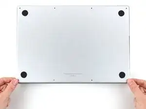
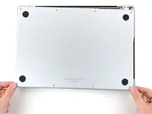
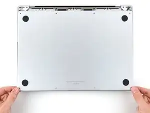
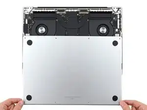
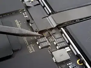
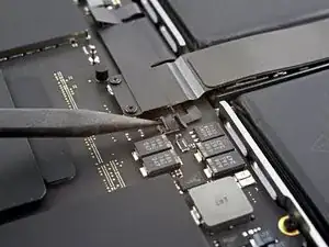
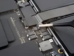
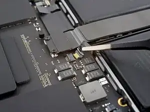
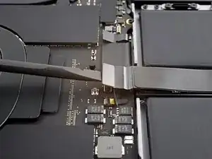
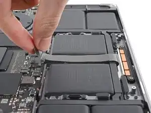
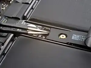
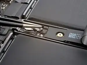
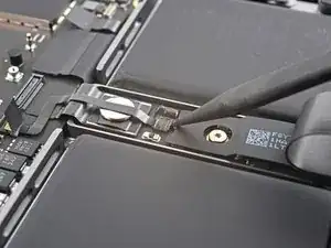
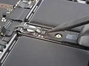
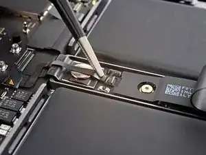
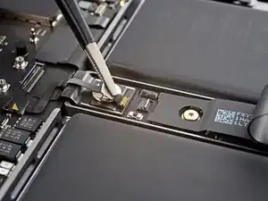
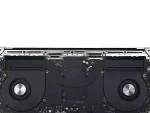
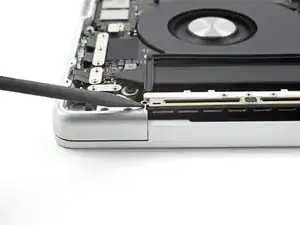
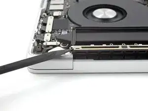
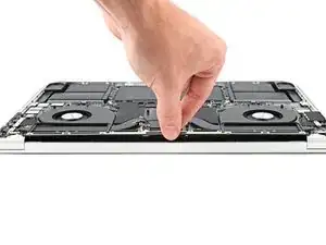
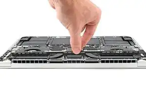
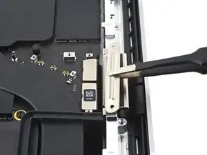
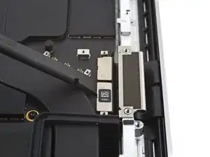
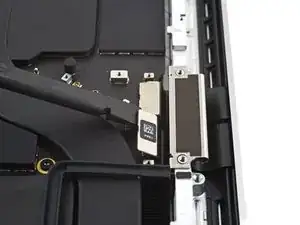
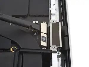
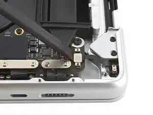
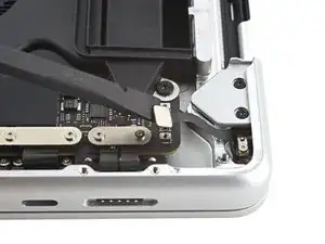
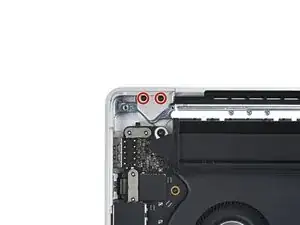
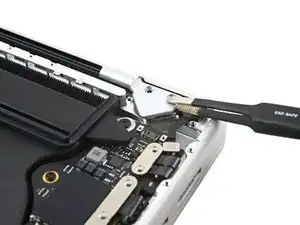
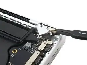
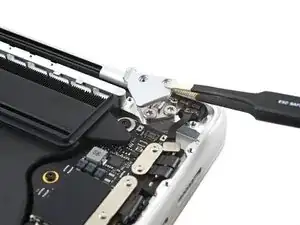
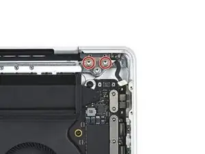
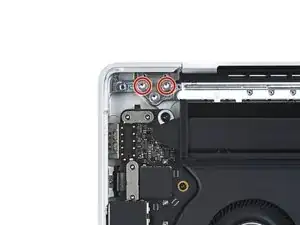
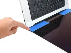
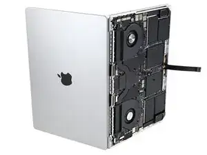
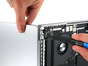
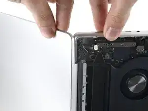
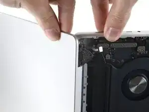
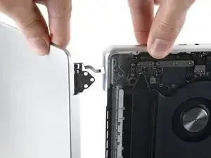
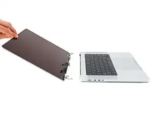
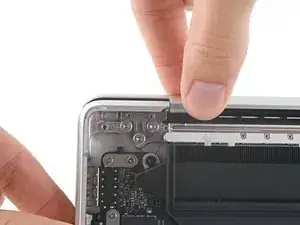
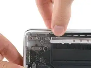
Use this guide to replace the screen in your MacBook Pro 14" 2023.

WARNING: While you can physically replace the screen by following this guide, replacement screens are known to display visual artifacts. Currently, the only available fix is Apple's System Configuration tool (which is only available through Apple when purchasing a genuine replacement screen). Alternatively, two soldered chips can be transferred between the screen controller boards.

For your safety, discharge the battery below 25% before disassembling your MacBook. This reduces the risk of fire if the battery is accidentally damaged during the repair. If your battery is swollen, take appropriate precautions.

Note: Replacing your screen disables True Tone functionality.

Some photos in this guide are from a different model and may contain slight visual discrepancies, but they won't affect the guide procedure.

  1. sAvCLYXqUkq3CpsT
    sAvCLYXqUkq3CpsT
    dYQhaLBJXSRTTctb
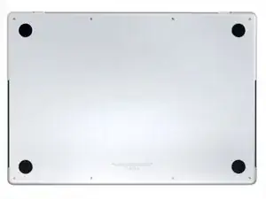
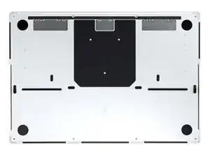
    • Completely power off and unplug your MacBook Pro before you start. Close the display and flip the entire laptop upside-down.

    • Use a P5 Pentalobe driver to remove eight screws securing the lower case:

    • Four 9.3 mm screws

    • Four 5 mm screws

    • Throughout this repair, keep track of each screw and make sure it goes back exactly where it came from to avoid damaging your device.

  2. XaNohnCmRnh2nZpJ
    XaNohnCmRnh2nZpJ
    vL2whH15EFx1twZH
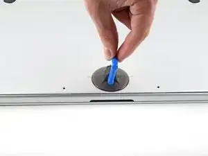
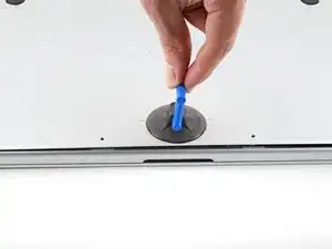
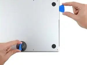
    • Press a suction handle into place near the front edge of the lower case, between the screw holes.

    • Pull up on the suction handle to create a small gap under the lower case.

  3. gKFYYs2sw4AKQjyZ
    gKFYYs2sw4AKQjyZ
    H4KsmKKCORb6oQgS
    XipK6OFYbtmB2HXx
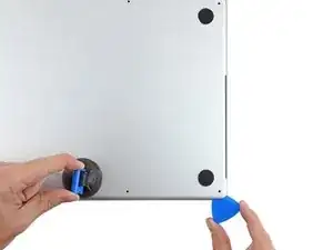
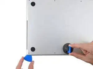
    • Insert an opening pick into the gap you just created.

    • Slide the opening pick around the nearest corner and then halfway up the side of the MacBook Pro.

    • This releases the first of the hidden clips securing the lower case. You should feel and hear the clip pop free.

  4. D6bdEaUShxT3UVIG
    D6bdEaUShxT3UVIG
    MUSM2IsQWQnMyLTY
    PVitYNF6oBIbr23x
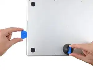
    • Repeat the previous step on the other side, using an opening pick to to release the second clip.

  5. jhQl23lkLmdIajyL
    jhQl23lkLmdIajyL
    5Biq1bJPZBQJR6co
    SosOCOgOT4DGPusW
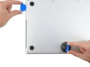
    • Pull firmly to slide the lower case towards the front edge of the MacBook (away from the hinge area) to separate the last of the clips securing the lower case.

    • Pull first at one corner, then the other.

    • Pull to the side—not up.

    • This may require a lot of force.

  6. Opome2xEF244Sbik
    Opome2xEF244Sbik
    Zhm2CbuWmJyMyRHI
    NZBNkwTekFWxsHvu
    • Remove the lower case.

    • To reinstall the lower case:

    • Set it in place and align the sliding clips near the display hinge. Press down and slide the cover toward the hinge. It should stop sliding as the clips engage.

    • When the sliding clips are fully engaged and the lower case looks correctly aligned, press down firmly on the lower case to engage the four hidden clips underneath. You should feel and hear them snap into place.

  7. SIIw4KNqNJat1yBq
    SIIw4KNqNJat1yBq
    CqRTAbjmiKvZwmLv
    6IUyFZNiLDUEWEX1
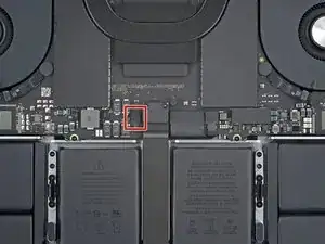
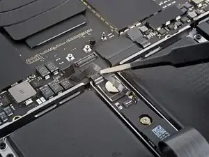
    • Peel back any tape covering the battery board data cable connector on the logic board.

  8. V4EqB5aHmr63xI1v
    V4EqB5aHmr63xI1v
    SQ1dKqsBDFs5moni
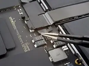
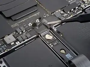
    • Use a spudger to gently pry up the locking flap on the ZIF connector for the battery board data cable.

  9. gRNLvpgBvrIRFj1o
    gRNLvpgBvrIRFj1o
    XeuVHmR3DERR3vvt
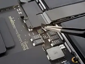
    • Disconnect the battery board data cable by sliding it out from its socket on the logic board.

  10. tWijJMdBI6gPL6ac
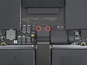
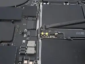
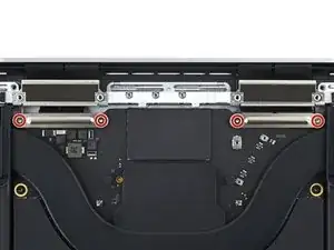
    • Use a T3 Torx driver to remove the two 2.1 mm‑long screws securing the trackpad cable bracket to the logic board.

    Sorry but this is not correct Apple procedure.

    There is power running through the device still whilst you are unscrewing this plate/bracket and disconnecting the trackpad if you do it this way. This is why Apple put the small flex cable next to this, free to reach before touching anything else.

    You must disconnect the battery flex cable next to the trackpad connector before you touch anything else.

    Thanks

    Brendan Roberts -

  11. WKgCgHbgW1ChnLeO
    WKgCgHbgW1ChnLeO
    AMVCrEnxxAlBZH1B
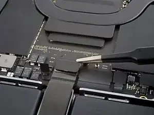
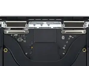
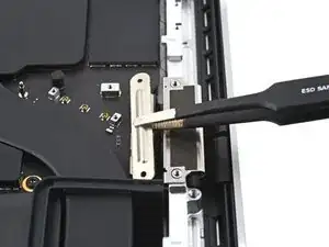
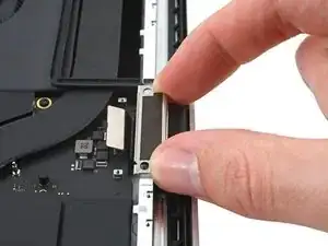
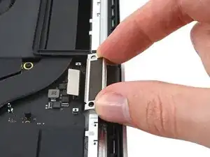
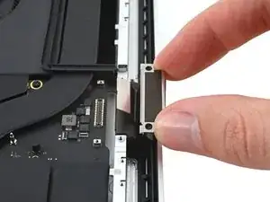
    • Use tweezers, or your fingers, to remove the trackpad cable bracket.

  12. HruGWCLaCDFQTy4i
    HruGWCLaCDFQTy4i
    lIj3sMFMZSYMtPJi
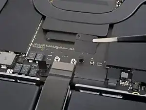
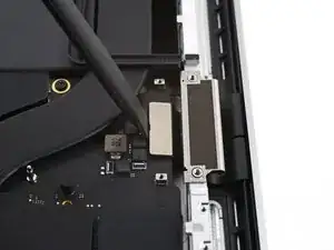
    • Use the flat end of a spudger to pry up and disconnect the trackpad cable's press connector secured to the logic board.

    • To re-attach press connectors like this one, carefully align and press down on one side until it clicks into place, then repeat on the other side. Don't press down on the middle. If the connector is misaligned, the pins can bend, causing permanent damage.

  13. odTkloRNKqkLFIy1
    odTkloRNKqkLFIy1
    WdEKjjUssSiSBQRr
    • The trackpad cable is lightly adhered to the frame.

    • Peel the trackpad cable away from the device, making sure to separate the adhesive.

  14. bmxLNFdBHc6VFNFG
    bmxLNFdBHc6VFNFG
    FjHbnTch3Jw2v4xP
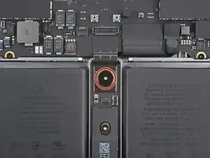
    • Peel back any tape covering the battery board data cable connector under the large pancake screw.

  15. YeVALkOj2MDGfUAD
    YeVALkOj2MDGfUAD
    YEDQCtAYmAeObXwb
    • Use a spudger to gently pry up the locking flap on the ZIF connector for the battery board data cable.

  16. CPVNHwGjCq5DHYlh
    CPVNHwGjCq5DHYlh
    OtDHIiOVv2ZSiqBE
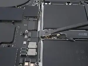
    • Disconnect the battery board data cable by sliding it out from its socket on the battery board.

  17. pZApKfPHIxQlREsA
    pZApKfPHIxQlREsA
    wttgdDPBHNlgcQNy
    • The battery board data cable is lightly adhered to the device.

    • Slide blunt nose tweezers under areas with adhesive to separate the cable from the device.

    • Remove the battery board data cable.

  18. FUOLA5NLVP3IPFZn
    • Use a T5 Torx driver to remove the 3.8 mm pancake screw securing the battery power connector.

  19. hvVm3YJcO2MRuHkK
    hvVm3YJcO2MRuHkK
    rFVOELLuBj2ZHQDt
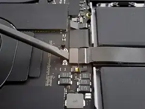
    • Use a spudger to lift the battery power connector, disconnecting the battery.

    • Lift the connector high enough to keep it separated from its socket while you work. If it accidentally makes contact, it could damage your MacBook Pro.

    I would place a piece of card stock (business card) taped to the battery cells so the contact can’t be made.

    Dan -

  20. qHXHOPIA3Nm5Z4Mx
    qHXHOPIA3Nm5Z4Mx
    RX1B6llNG3REKEGx
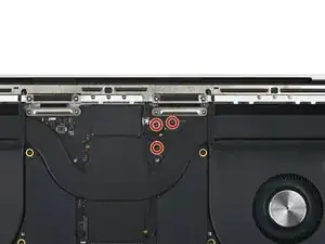
    • Use a T3 Torx screwdriver to remove the three 2.1 mm screws securing the antenna board bracket and coaxial cable cover to the frame.

  21. NISpyifFwBadkYRn
    NISpyifFwBadkYRn
    wAKrsORhDY21Sbuf
    • Use tweezers, or your fingers, to remove the cover on top of the antenna bar's coaxial cables.

  22. QsvVGWDNUgWL2tAm
    QsvVGWDNUgWL2tAm
    kc1Tm3DP5RFVIoGJ
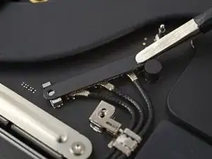
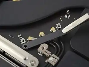
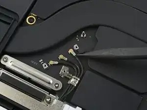
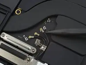
    • Use the tip of a spudger to pry up and disconnect the antenna bar's coaxial cable.

    • Repeat for the two other cables.

    • During reassembly, these can be tricky to reconnect. One at a time, hold each connector in place over its socket and press down with the flat end of a spudger. The connector should snap into place.

  23. QG5nkErfOYmMPwfP
    QG5nkErfOYmMPwfP
    FYJGYThTWbXy3HOF
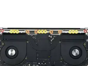
    • Use a T5 Torx screwdriver to remove the six screws securing the antenna bar to the frame:

    • Two 7.5 mm screws

    • Four 3.2 mm screws

    • Use a P2 Pentalobe driver to remove the nine 1.5 mm screws securing the antenna bar to the frame.

    • These screws strip very easily; use constant downward pressure and work slowly when you loosen these.

  24. 4KXaRPXBXyemFIae
    4KXaRPXBXyemFIae
    QlWUGmx6FDGauRxp
    • Insert the tip of a spudger between the antenna bar and the frame.

    • Pry up with the spudger to separate the antenna bar from the frame.

  25. ewF6AEhufwb53IHS
    ewF6AEhufwb53IHS
    6QKNeMlitQ3K54vC
    • Pull the antenna bar straight up and out of the frame to remove it.

  26. HmnoNBvWLm6tZEqB
    HmnoNBvWLm6tZEqB
    DTUULHJ3jgM2KHKx
    • Use a T3 Torx driver to remove the four 2.1 mm screws securing the display cable covers.

  27. AlZTNpXrnKCED5cP
    AlZTNpXrnKCED5cP
    rEaeYwEYMRDd3KUS
    • Use tweezers, or your fingers, to remove the two display cable covers from the logic board.

  28. iGLZDr6x3fcOoSdA
    iGLZDr6x3fcOoSdA
    QoKvLDMrNMfIrIjR
    WRVYbhNYbW4N1jEx
    • Use the flat end of a spudger to pry up and disconnect the two right-most display cable press connectors secured to the logic board.

  29. nd1ANiturmExTbJ6
    nd1ANiturmExTbJ6
    awfFUOcBChlpEAOu
    • Repeat the previous step for the left-most press connector.

  30. 2JGRJb6FneQSFHud
    2JGRJb6FneQSFHud
    jMWdk4YGXDWhnDp2
    6aOry1sKEFLy4DTS
    • Pull up on the back of the display cable bracket to release the clips securing it to the frame.

    • Remove the display cable bracket.

    • Repeat for the other display cable bracket.

  31. KULnxFpPK6DEIgVB
    KULnxFpPK6DEIgVB
    CfYwnYmB6nnGr3vp
    • If the two display cable bracket buffers are removed alongside the brackets, then skip this step.

    • Pull the two display cable bracket buffers straight up and out of the frame to remove them.

  32. nU4vyumR2oRPuaCS
    nU4vyumR2oRPuaCS
    OTeZrglWMhtG3yqe
    • Use a T3 Torx driver to remove the two 2.1 mm screws securing the lid angle sensor cover near the right hinge.

  33. ySdYkAvPTeNpnfUy
    • Use tweezers, or your fingers, to remove the lid angle sensor cover.

  34. 3KVZiV1tnfFGagno
    3KVZiV1tnfFGagno
    YmxKBWWb6rwTKWQD
    • Use the flat of a spudger to pry up and disconnect the lid angle sensor's press connector.

  35. OO3WXlt5bvYI5LRs
    OO3WXlt5bvYI5LRs
    VjwDUR4V23D2ROXd
    • Use a T5 Torx driver to remove the four 2.5 mm screws securing the hinge covers (two screws on each side).

  36. RYfHBwuYeqCM2Aj4
    RYfHBwuYeqCM2Aj4
    CTPX1AQVV1gyMGpW
    KanI5vuSACUnAJNa
    • Use tweezers to pull the hinge covers horizontally away from the hinge to separate it from the frame.

    • Remove the hinge covers.

  37. bKaPYeeyPjlAWn5J
    bKaPYeeyPjlAWn5J
    1u3ZBfElVSVxdEMX
    • Use a T8 Torx driver to remove two 5.2 mm screws from each hinge (four screws total).

    • Each hinge has a third screw, which you should leave in place for now.

  38. dAHYNPOxARHeWpRs
    dAHYNPOxARHeWpRs
    KA556FCTuJc5Vrn3
    • If you plan to re-use your screen, open it and apply a piece of tape to the glass directly above each hinge. This helps protect the glass from getting scratched in the following step.

    • Fully open the screen and stand your MacBook Pro up on one side.

  39. WV6SC2Is3ihfYAjI
    WV6SC2Is3ihfYAjI
    jkdL6IpciW4K3UJW
    wdeMKDnFV6lABHjG
    • Use a T8 Torx driver to remove the two remaining 5.2 mm screws (one from each hinge).

    • Remove the topmost screw last, using one hand to steady both halves of the MacBook Pro to make sure they don't separate and fall over unexpectedly.

  40. IMM3limP1GumvBZL
    IMM3limP1GumvBZL
    BQdVBNrR4fkQScab
    IJo2ODH3HDDxHkxP
    • Keep a firm grip on both the screen and main body of the MacBook Pro. Either half can fall unexpectedly during this step.

    • Push both halves of the MacBook Pro together so that the hinges can be lifted clear of their recesses in the chassis.

    • Push the main body of the MacBook Pro away from you while pulling the screen toward you to separate it.

  41. FNnhxexVSBfitTmr
    • Remove the screen.

  42. FEbGVqhmIuaBH3ZW
    FEbGVqhmIuaBH3ZW
    U4PtkM5gVmCSPkYb
    • During reassembly, first install the hinge screws without tightening them fully. Then adjust the screen until it is correctly centered and aligned on each side. Finally, tighten the screws.

    • If your screen clicks or snaps upon opening, loosen the hinge screws and adjust the alignment. Make sure the screen doesn't sit too far forward, or it can catch on the body when opening and closing.

    • If desired, add a little blue threadlocker to the screw threads to prevent them from loosening over time.

    Hallo,

    ist jemanden bekannt dass nach Display Austausch oberhalb des Display Karos zu sehen ist?

    Muss dieser Display nach Tausch programmiert werden?

    Vielen Dank für Beiträge!

    Senol Biyikli -

    ja, ohne alte MCU oder Apple Software funktioniert es nicht wirklich sauber, nur mit Pixelfehlern. Ich mag solche "anleitungen" - nie wirklich selbst probiert, aber so viele schöne Bilder, yay.

    RipperDoc -

Abschluss

To reassemble your device, follow these instructions in reverse order.

Compare your new replacement part to the original part—you may need to transfer remaining components or remove adhesive backings from the new part before you install it.

Repair didn’t go as planned? Try some basic troubleshooting, or ask our MacBook Pro 14" 2023 Answers community for help.
Chayton Ritter

Mitglied seit: 21/08/20

12163 Reputation

0 Kommentare