Einleitung
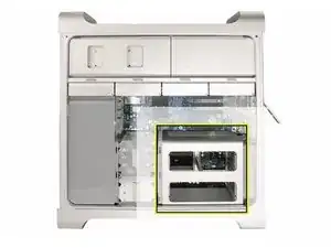
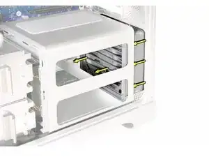
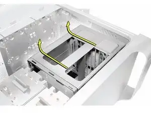
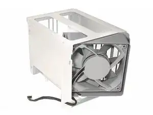
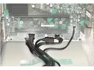
Removing and/or replacing the Memory Cage with Rear Fan.
Werkzeuge
-
-
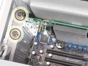
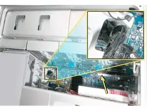
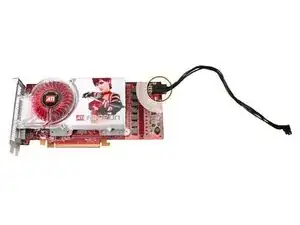
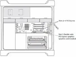
This procedure explains how to remove a standard card and a card that includes a booster cable. Before you can remove either type of card, however, you must first loosen the two captive screws that secure the PCI bracket to the enclosure and remove the bracket.
-
-
-
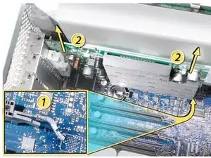
1) Release the small locking clip at the front of the card’s logic board connector by pushing the clip up toward the media shelf.
-
2) Holding the card by the top corners, pull up the card and remove it from its expansion slot.
-
-
-
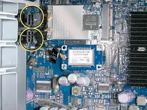
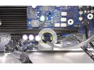
Disconnect the booster cable(s) from the logic board.
-
Release the small locking clip at the front of the card’s logic board connector by pushing the clip up toward the media shelf.
-
Holding the card by the top corners, gently pull up the card and remove it from its expansion slot.
-
-
-
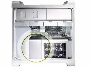
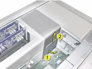
Place the fingers of one hand under the lip of the heatsink cover nearest the logic board. Lift the lip slightly toward the media shelf to release the tabs and magnets under the top face of the cover.
-
With your fingers still under the cover’s bottom lip, lift the cover straight up to release the remaining tabs and magnets under the front face of the cover
-
Remove the cover from the enclosure.
-
-
-
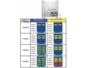
800 MHz, DDR2, FB-DIMMS
-
72-bit wide, 240-pin modules
-
36 memory ICs maximum per DIMM
-
Error-correcting code (ECC)
-
-
-
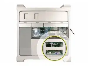
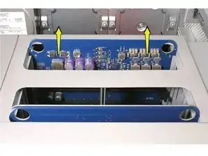
Holding the memory riser card by the two finger holes, pull it out of the memory cage and place the card DIMM side up on a soft, clean cloth.
-
-
-
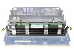
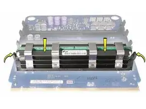
Open the ejectors on the DIMM slot by pushing them out to the sides, and remove the DIMM from the riser card.
-
-
-
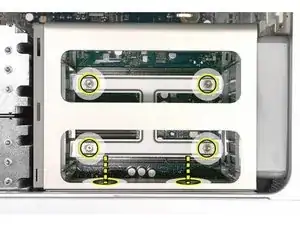
Using a long-handled, magnetized #1 Phillips screwdriver, loosen the four captive screws that mount the memory cage to the logic board.
-
Rotate the computer so that it is standing vertically. Using a magnetized short-handled or right-angled jeweler’s #1 Phillips screwdriver, carefully remove the two short screws that mount the memory cage to the bottom panel of the enclosure.
-
-
-
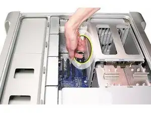
Using your forefinger, reach below the fan and release the latch nearest the logic board.
-
-
-
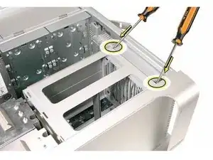
Using a flat-blade screwdriver, release the two latches nearest the front of the computer.
-
-
-
Slide the memory cage and fan toward the power supply far enough that the cage clears the bottom edge of the enclosure. Then lift the memory cage and fan out of the enclosure.
-
To reassemble your device, follow these instructions in reverse order.
