Einleitung
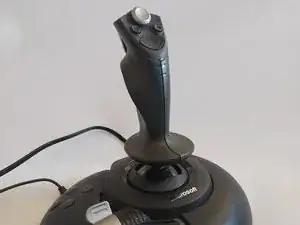
This guide will show how to access and replace the # 1 (Trigger), 2, 3, 4, 9-12(Hat) button switches. Be aware you will need basic soldering skills and equipment prior to attempting.
Ersatzteile
-
-
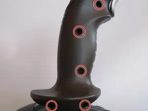
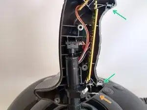
Remove (5) Philips head screws on the Stick Body. The bottom two will require a longer reach than a typical exchangeable bit-type screwdriver provides.
-
-
-
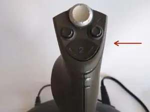
Separate the two halves of the stick body while keeping the Hat, #1 (trigger) and #2 buttons from falling out and becoming lost.
-
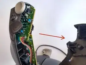
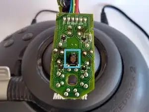
Two printed circuit board's, one for the switches, one for the infrared sensor, as well as the rudder rotation encoder are now exposed. The PCB's are friction fit into the casing halves, so they can be removed by hand with little to moderate force. Be careful of the wiring.
-
Be mindful not to bend the rudder spring nor disturb the lubricant at the bottom of stick.
-
Be careful of the leads for the Infrared LED and photodiode.
-
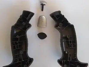
Set aside the casing halves, Trigger, Hat, and #2 button.
-
-
-
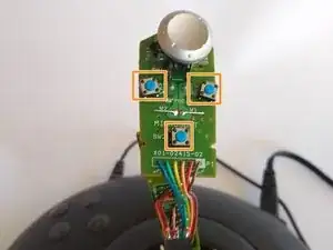
With the halves of the stick removed, the circuit boards are exposed.
-
(3) 6x6x4.3mm momentary switches for buttons #2, 3, 4. Omron B3F-1002 or equivalent.
-
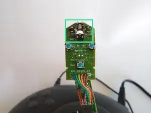
(4) 6x6x4.5mm right angle momentary switches for the Hat buttons #9, 10, 11, 12. Omron B3F-3122 or equivalent.
-
(1) x 6x6x7.3mm switch for Trigger button #1. Omron B3M-6009 or equivalent.
-
-
-
This step will require a soldering iron, solder with flux, solder vacuum and/or solder wick. I highly recommend learning soldering and de-soldering for through-hole components before attempting, this is not an easy first soldering experience.
-
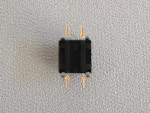
Use soldering iron to heat the existing solder joints to flowing, and then apply wick or solder vacuum to remove solder. Once sufficient solder has been removed, the inoperable switch can be removed from the PCB. Take note of the orientation of the removed switch by viewing the raised lines on the bottom of the switch.
-
Insert new switch into PCB while matching of the orientation of the removed switch. The raised straight line(s) should be in the same direction as the removed switch's straight line(s).
-
To reassemble your device, follow these instructions in reverse order.