Einleitung
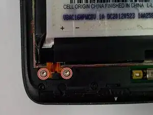
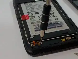
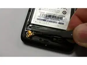
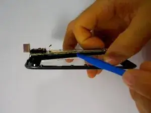
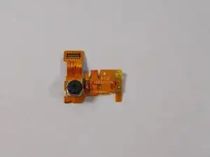
The cameras of the Atrix HD are protected by the housing of the phone, but they can be damaged by exposure to moisture, impact, or scratches. If your photo quality is suffering it may be time to replace the affected camera. With just two tools, you can be back to taking high-quality photos in no time.
Werkzeuge
-
-
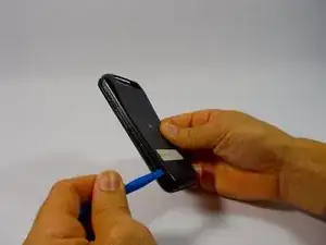
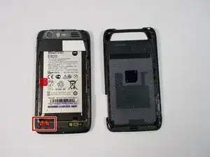
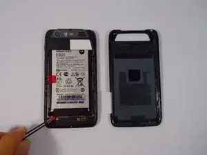
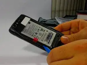
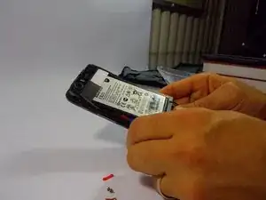
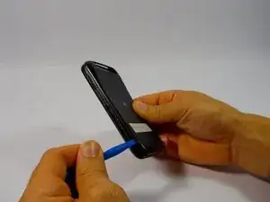
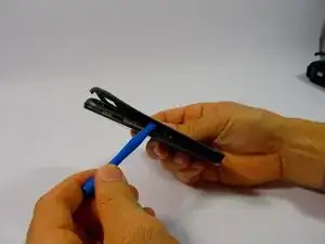
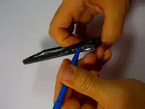
Begin taking apart the device by prying apart the back cover from the assembly using the plastic opening tool.
-
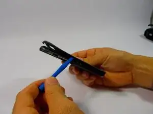
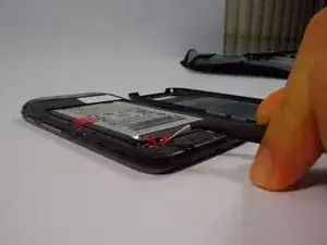
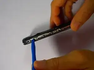
Continue working around the edge of the phone using the plastic opening tool.
-
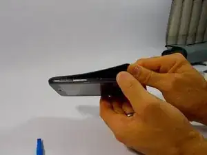
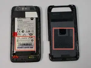
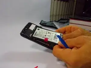
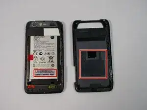
When all the edges have been lifted apart, use your hands or plastic opening tool to peel the back plate from the battery. There are small adhesive strips between the back cover and the battery, so take care not to crack the back cover while prying open.
-
-
-
The adhesive strips are shown in the orange boxes. Be sure not to use too much force to pull off the back cover, or you may risk snapping the back cover.
-
-
-
Use the plastic opening tool around the edges to loosen the battery.
-
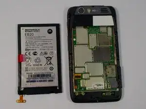
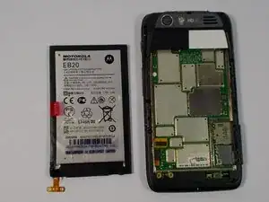
Once the battery is loose, carefully lift from the bottom edge and remove the battery.
-
-
-
Begin by removing the back cover using the plastic opening tool. There are adhesive strips attached to the back cover, so take care when prying case to prevent cracking
-
The adhesive strips may stay on the back cover or the battery.
-
-
-
Now with the screws removed, use the plastic opening tool to lift the edges of the front assembly.
-
Continue to use the plastic opening tool around the edges of the device to remove the front assembly.
-
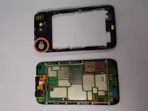
The speaker is located in the upper corner of the case. It it attached with adhesive and can be removed by gently prying with the plastic opening tool
-
-
-
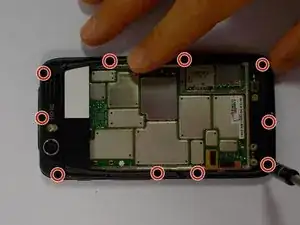
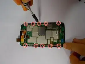
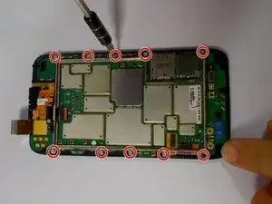
Begin by removing the 10 Torx T5 motherboard baseplate screws
-
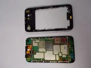
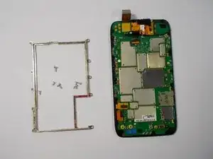
The back chassis can now be removed.
-
-
-
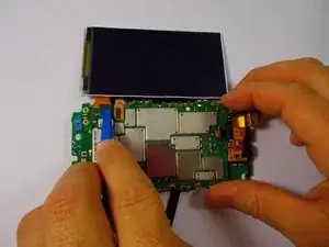
After following the steps to access the motherboard, you are ready to remove the touchscreen and LCD display.
-
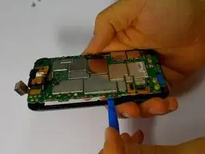
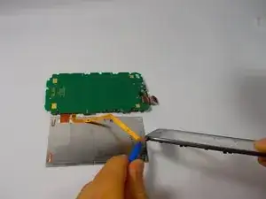
Use the plastic opening tool to separate the LCD display from the motherboard.
-
-
-
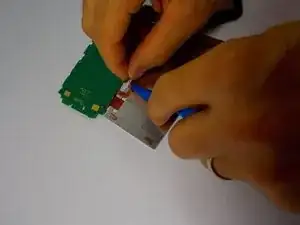
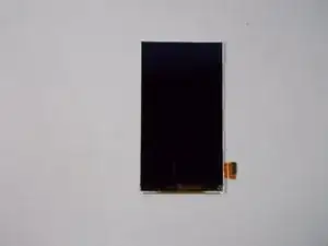
Remove the ribbon cable from the back of the lcd using the plastic opening tool or spudger.
-
-
-
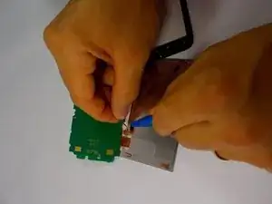
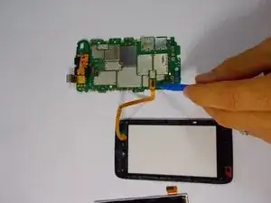
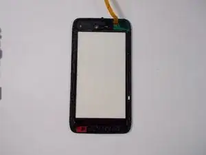
With the LCD display removed, remove the ribbon cable connecting the touchscreen to the motherboard
-
-
-
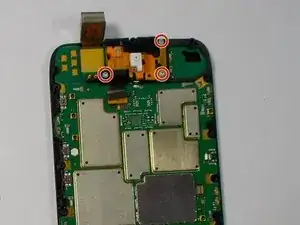
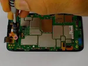
Remove the three Torx T5 screws that locks the front facing camera to the motherboard.
-
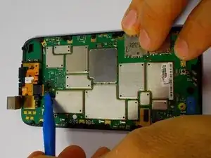
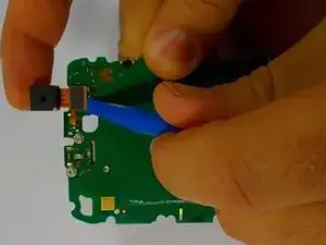
Use the plastic opening tool to lift the ribbon cable from the motherboard.
-
-
-
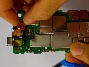
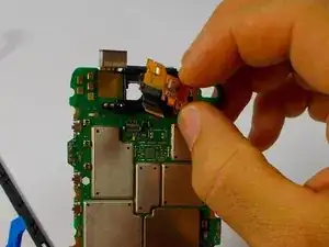
Use the plastic opening tool to lift the ribbon cable connector from the motherboard.
-
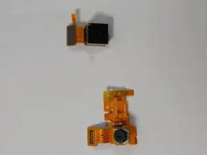
Now both front and rear cameras have been removed.
-
To reassemble your device, follow these instructions in reverse order.
