Einleitung

This guide will take you through the process of installing a new front panel on your Motorola Droid.

  1. WDWd444xZb13qRKn
    WDWd444xZb13qRKn
    2ktKHy6xMckvSmdW
    gZ5YVobJYePNrPIu
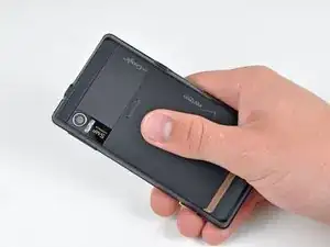
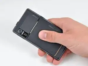
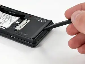
    • Slide the battery cover downwards while applying pressure to the center of the battery cover with your thumb.

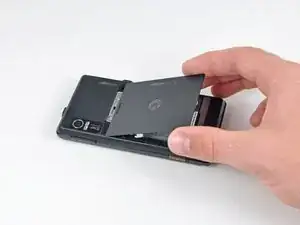
    • Lift and remove the battery cover out from the phone.

  2. UpO3BpUfqTeE6X2N
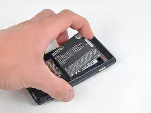
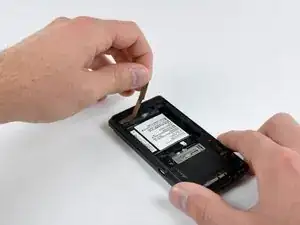
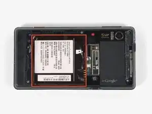
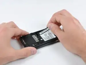
    • Grasp the upper left corner of the battery and lift it out of its housing.

  3. GIDMJhy4j5mNg1cG
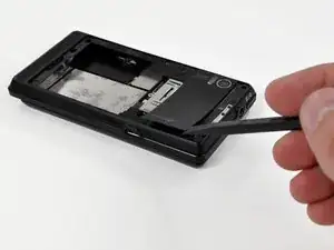
    • Use a spudger to lift and remove the black plastic screw cover at the top of the phone near the camera.

    • The cover is attached by adhesive, so some force may be required.

    This is actually extremely difficult to do with the plastic spudger pictured. I was forced to use the thin sharp tip on a metal spudger to get any leverage, which slightly damages the plastic.

    Robert Ciaccio -

  4. aBF3XFsSNutCkpUd
    aBF3XFsSNutCkpUd
    VQTksVMeEWYLLOI2
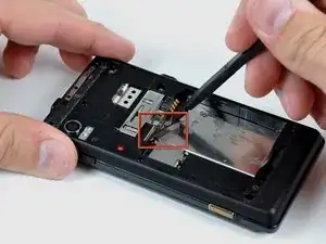
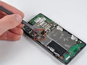
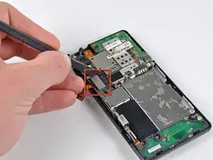
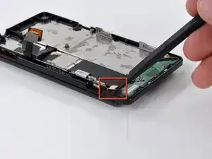
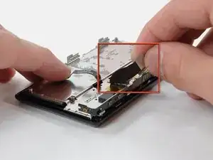
    • Using the tip of a spudger, peel up one corner of the gold ribbon beneath the battery compartment.

    • Peel the ribbon up off the phone.

  5. 16MDCKUg4J5TXyG1
    16MDCKUg4J5TXyG1
    B3NNyNP1Jfw53EV4
    • Carefully peel the device information label that covers the motherboard EMI shields.

    • This label contains important information specific to the phone. Remove it with care and keep it in a safe place.

  6. sZVXJcq44YuspQoO
    • Insert the flat end of a spudger and pry the plastic camera cover up off the phone.

    • The thin plastic cover is attached to the phone with an adhesive. Work slowly and carefully.

  7. UuZnOchnYrwyRXZH
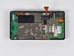
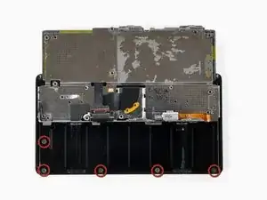
    • Remove the seven 5.5 mm T5 Torx screws securing the rear case to the inner case.

  8. C4jmmk6kK2fAmsLZ
    • Insert the flat end of a spudger and pry downwards to release the plastic tab holding the rear case to the motherboard screw.

  9. 2S2OZQYFAeNw2jLA
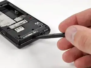
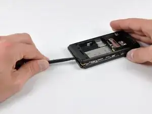
    • Gently insert a spudger between the rear case and front case at the top of the phone, near the audio jack.

    • Carefully pry the top edge of the rear case up from the rest of the phone.

  10. OLVIHHQfpRLGmLUE
    OLVIHHQfpRLGmLUE
    hvdebIlPLntc6vqm
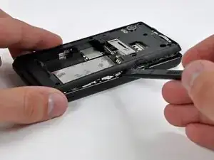
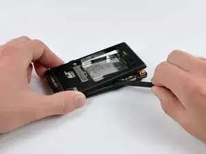
    • With the spudger still inserted between the rear case and front case, slide the spudger along the right edge of the device, moving toward the bottom, prying as you go.

    • Continue prying along the bottom edge of the device from right to left, freeing it from the front panel.

  11. LdwIk4vNbDBuspAf
    LdwIk4vNbDBuspAf
    dKXHSwthUGQWMLxM
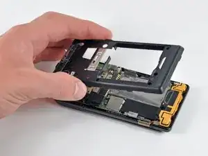
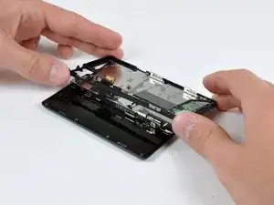
    • Continue prying the rear case from the front case along the left side, moving from bottom to top.

    • Lift the rear case up out of the phone.

  12. QLowZ16K1rXRqQXa
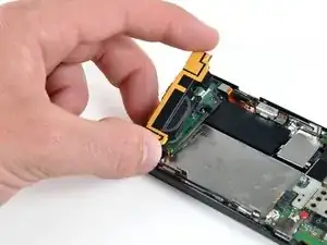
    • Carefully lift and remove the speaker assembly up out of the phone.

  13. twvST3tGsKc5Js6D
    twvST3tGsKc5Js6D
    KvZu2RGtf1WMlYFW
    NfFFTsBuIacASnNE
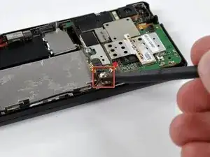
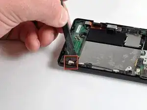
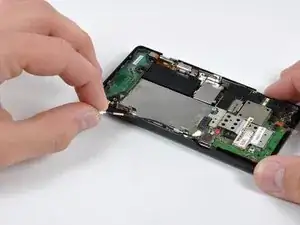
    • Use a spudger to pry the antenna cable connectors from their respective sockets on the motherboard and the speaker/antenna board.

    • De-route the antenna cable by pulling it out of the metal clips along the side of the front case.

  14. JQeQuvGDbPYTAvLX
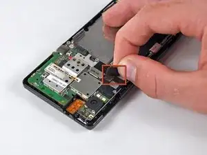
    • Peel the black tape covering the side button and display ribbon connectors on the motherboard.

  15. gQCNCCmbplYe1AgL
    • Disconnect the power button/volume button connector from its socket on the motherboard using the flat end of a spudger.

  16. JPwqrbCCTwdNupjE
    • Disconnect the display ribbon connector from its socket on the motherboard using the flat end of a spudger.

  17. lwQbKnYUqKH6FndD
    • Remove three 3.8 mm T5 Torx screws securing the motherboard to the front case.

    • Don't attempt to remove the motherboard yet, it is still attached by the keypad ribbon connector.

  18. UbBdhUHLcd1MfExh
    UbBdhUHLcd1MfExh
    dUc2ZDl22loWVfJs
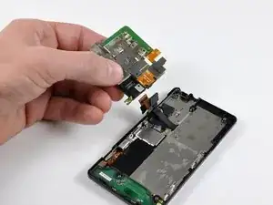
    • Carefully lift the motherboard from the front case and lay it next to the Droid, minding the keypad connector that is still attached.

    • Disconnect the keypad connector by prying it straight up off its socket on the motherboard.

    • Remove the motherboard from the phone.

  19. 5FfeSZAyj5DRD2HS
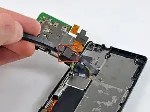
    • Disconnect the camera button/vibrator connector by prying it straight up off its socket on the speaker board with a spudger.

  20. 3gbY4LyLdGFiHx1H
    3gbY4LyLdGFiHx1H
    kDeRiGGRAXKvOPDi
    • Slide the phone open.

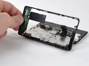
    • Lift up the edge of the black plastic rim that includes the speaker board from the side closest to the keypad.

    • Continue lifting the side of the rim until it is almost vertical, and wiggle it free from the back of the LCD assembly.

  21. iCJ3pTEW11vNqrSK
    • Remove the EMI shield by releasing the clips shown with the tip of a spudger.

    The "EMI Shield" isn't really an EMI shield so much as a guide for the display cable - it ensures the cable folds up correctly during actuation. Don't leave it out and replace it carefully when you reassemble.

    Matthew Roy -

  22. TNSPlOtFQ4VJOg6Z
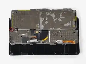
    • Remove the five 2.5 mm Phillips screws.

    • It's either a 2.5 MM Phillips or a T4 Torx. Motorola changed it on later models of the A956.

    These screws are insanely difficult to remove. I was stuck with three stripped screws.. still thinking of solutions to remove these. It may be time to break out the drill and drill through the screws. Then, I'll reseal it with crazy glue and hope to never have to take it off again.

    Joshua Kornblum -

    You are right, Joshua! They were nearly impossible to remove. I was finally able to get them out by (1) placing the device screen-down on a hard work surface, (2) fitting a metal phillips head screwdriver of the correct, tiny size into a screw, and (3) hitting the end of the screw driver soundly 3 times with a pair of pliers. Then (4) I held the screw driver firmly in the screw with signifigant downward force and turned the device clockwise while not allowing the screwdriver itself to turn. Before I discovered that procedure I trashed two screwdrivers and messed up the screw heads pretty badly. nevertheless it worked. I have not yet tried to put them back in.

    Lamoid -

  23. wTDgvMc2SZbtjByr
    • Slide the phone until a sixth screw is visible, as shown.

    • Remove the single 2.5 mm Phillips screw.

  24. CIb4Nwig2BjTXkRP
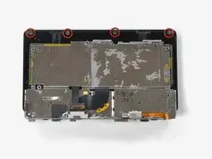
    • Continue sliding the phone in the same direction, past its "closed" position, until four more screws are revealed. You will need to lift the slider slightly to get it passed the "closed" position.

    • Remove the four 2.5 mm Phillips screws.

  25. a4ioCwNJrSt1yZow
    • Return the phone to its normal "closed" position.

    • Peel the display ribbon up from the keypad's metal backing.

    • The ribbon cannot be completely removed yet, because it is attached to the back of the LCD.

  26. TVgff5KPBLESYYAE
    TVgff5KPBLESYYAE
    UvBT1ALBqT6uab3H
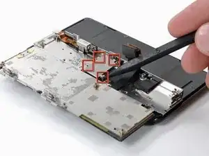
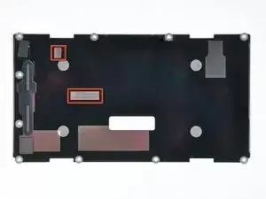
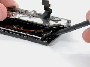
    • Insert a spudger between the back and front case of the display assembly, and peel the two ribbon cables off the two adhesive pads along the back case of the display assembly.

    • The location of the pads on the back case is shown. The top left corner of the case is the corner of the phone shown in the first picture.

    I failed here. I accidentally ripped off the front panel connector. Because i lifted both sides too far up.

    Up until then, all went rather smooth. Be careful with the thin, flat connections, they can rip off easily.

    Tom Brewe -

  27. jvI5hqXWPYvZAXBh
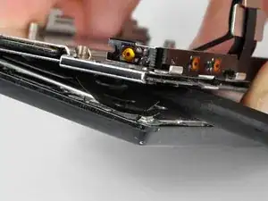
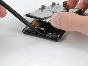
    • Use the flat end of a spudger to lift the board that contains the ambient light sensor and display data cable connector out of the screen housing.

  28. iHNZKAtkEIv1IBj3
    iHNZKAtkEIv1IBj3
    G2BVIMAwRYZE6XRP
    • Use the tip of a spudger to lift the speaker out of the screen housing.

  29. KBLa42JIRl1VMowc
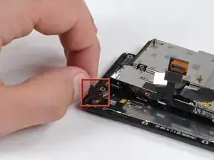
    • Peel off the black tape to reveal the front panel connector.

  30. yjJFGKWJKmgAnCdV
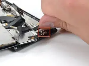
    • Use the flat end of a spudger or your fingernail to flip up the retaining flap on the front panel ribbon cable ZIF socket.

    • Be sure you are prying up on the hinged retaining flap, not the socket itself.

    • Disconnect the front panel ribbon cable.

    It's not clear in the picture, but that little black piece on the ZIF display connector flips UP. Use a small screwdriver/spludger and flip it away and up from the edge of the phone.

    Matthew Roy -

  31. KGvqfKqpZQBMH2ri
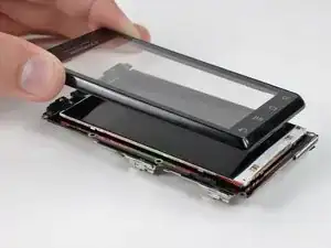
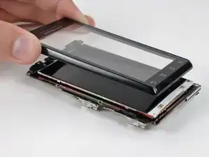
    • Flip the phone over and remove the front panel.

    Thanks for this guide :)

    My screen broke and I successfully replaced it with the new one.

    The most difficult was to separate LCD screen and the front panel.

    Natalia Demyanenko -

    During my repair, the front panel did not easily release from the LCD -it may have been glued in place. I needed to replace the smashed digitizer WITHOUT damaging the LCD panel underneath.

    My solution was to push the digitizer out from behind. I did this by sticking a small screwdriver through the small opening for the 'front panel ribbon cable' as featured in step 30. This did not damage my LCD as this opening is above where the LCD is mounted, near the speaker and ambient light sensors.

    Erik -

Abschluss

To reassemble your device, follow these instructions in reverse order.
David Hodson

Mitglied seit: 14/04/10

148365 Reputation

0 Kommentare