Einleitung

Use this guide to replace the rear camera on your Motorola Moto E 2nd Generation.

  1. vSEJAHYjTlZBPKOC
    • Turn off the device before beginning your repair.

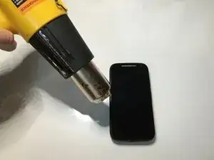
    • Using a heat gun, carefully apply heat around the edges of the display to soften the glue. Heat should be applied to the point where the phone isn't too hot to touch, but close enough.

  2. kLamGKmEOyFNs3GM
    kLamGKmEOyFNs3GM
    aggUQx2wdMDFwIiY
    qpGKGDZ26pRW3mRX
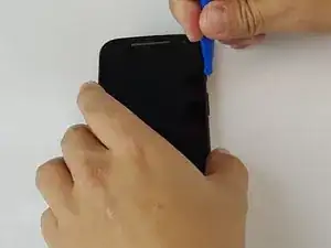
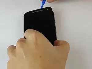
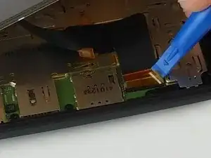
    • Using the small plastic opening tool, pry and slide all the way around the phone while carefully lifting up on the display.

    • The screen is secured by two-sided tape located on the edge.

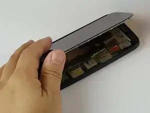
    Do not lift the screen too far or you may tear the LCD connection flexi. Check next images to see where it is, bottom and opposing side to the buttons

    MW Wilson -

  3. fGl22FZMPjdO4UJv
    fGl22FZMPjdO4UJv
    PTEVageZVB2TYToY
    uMn4q6XjCl5htfdw
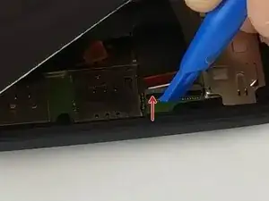
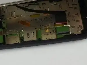
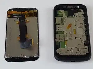
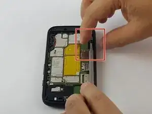
    • Once display is fully unglued from the frame, carefully lift it up and locate the display connector.

    • Using the same small plastic tool, carefully remove the yellow tape off the connector.

    • Now carefully undo the black connector lock by lifting it up in the direction of the red arrow.

    • Do not pry on the gray part of the connector.

    • Lastly slide the display cable off the connector. It should easily slide off, if not make sure the black lock is fully unlatched.

    Very well put together. Worked fine for me.

    A guitar pick will work as well as the plastic tool, but it might be a little harder to work with.

    Jon Gregory -

  4. 4cuqeG3P1W3TPZE4
    4cuqeG3P1W3TPZE4
    W6qcrwwmoNPwXNGH
    5rbTrEsHPG2gINNE
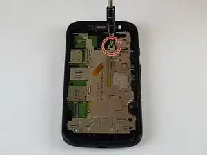
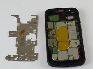
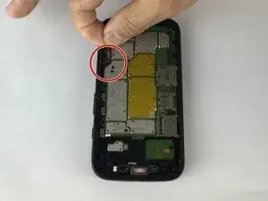
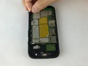
    • Now that the display is out, remove the aluminum shield off the motherboard.

    • Unscrew the single 4mm screw located on the top using a T4 Torx bit.

    • After screw is out, gently remove the aluminum shield off the motherboard.

    • Working on a magnet board is recommended as the screws are small and can be easily misplaced.

  5. VFVxrNushQoFPjRx
    VFVxrNushQoFPjRx
    fPst6DM1Dyq6kLSS
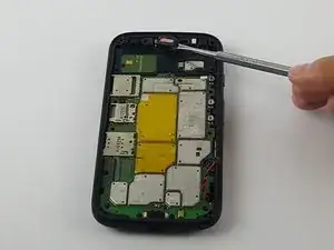
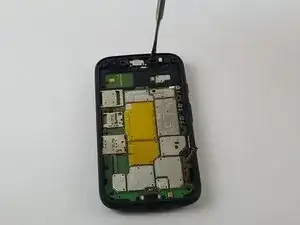
    • Using the metal spudger tool, very carefully remove the speaker by first gently prying up on the right side and then the bottom.

    • The ear piece is held by double sided tape and clips to the motherboard so be very careful.

    You can see a plastic clip on the right, so I understand the justification for prying on the right first. However, when I tried prying on the right, it separated the two halves of the speaker, ruining it. There was also a pad of foam, double sided tape under mine.

    Paul K -

    If you see in the other side the plastic clip is smaller , I was able to release this clip (the left side one) and in the bottom part of the speaker you can see a little gap when i put my pointy metal spudger and help the speaker slowging going up, it fells a little hard to push because of the magnet in it.

    Jose Carlos -

    I found I did not need to remove the speaker. I was able to (just barely) reach the screw behind it without removing it. After removing all of the other screws, I loosened that one a little bit at a time while gently prying the motherboard out of the case. Eventually it was all the way removed and I was able to take out the motherboard.

    David -

    Great tip about not removing the speaker. I, too, managed to remove that screw behind the speaker. I didn’t even need to pry out the motherboard while doing it.

    Keith R -

    Is the T4 Torx bit the one with the hole in it?

    Lynette -

    I think you may be referring to a security torx bit. These screws just need standard torx bits, although a security one should work too. Lookup torx on Wikipedia and impress/bore your friends for evermore.

    Keith R -

    Sir need track diagram for this………… speakers track might be cut….

    Harsh Kadam -

  6. xeVApjLjmNGCUgZr
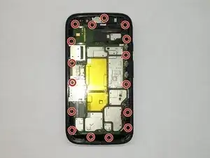
    • Unscrew the remaining 16- 4mm screws using a T4 Torx bit.

    • Using a magnet board is recommended as the screws are small and can be easily misplaced.

  7. DqCfv5JUUXFHVMSJ
    DqCfv5JUUXFHVMSJ
    OQWnJ4F4ZiFQtGiD
    RTdbEHbZJ4RZDHN6
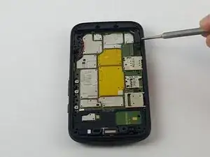
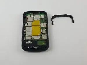
    • Next remove the plastic C-shaped black plastic frame.

    • Using the metal spudger tool, gently pull up the right corner as indicated and work your way around until it's off the motherboard.

  8. HdXfweQbEHy1qVwZ
    HdXfweQbEHy1qVwZ
    u4B5cAbI5T6dMBwO
    • Gently lift up the battery cable connector, it should come out very easy.

  9. V4RBPICUwDo62pis
    V4RBPICUwDo62pis
    TbqfsACnu4frv1TQ
    oiKcqZWi3RChjpc1
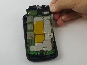
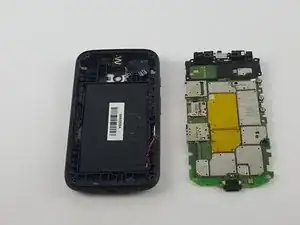
    • After the battery cable is disconnected from the motherboard, use the metal spudger tool and carefully insert it in the small opening by the speaker and pry the motherboard up enough to fit your finger in between the motherboard and the phone frame.

    • Now just pull the motherboard starting from the top to bottom off the phone case.

  10. CNsPJBJkHPlSEfcy
    CNsPJBJkHPlSEfcy
    fVQcpILGbZ3KSypw
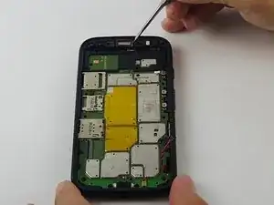
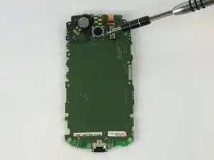
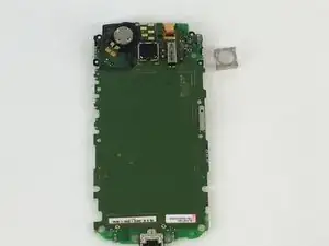
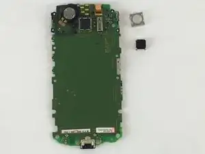
    • Using a spudger (ignore the pictured screwdriver), pry up the metal square frame on each side until it comes off.

  11. BkyA6q4IGPKgvudG
    BkyA6q4IGPKgvudG
    OPhK3B3NMJlqwl4J
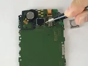
    • Once the metal square frame is out, use the same tool to pry up the camera by gently pulling on each side until it comes off

Abschluss

To reassemble your device, follow these instructions in reverse order.
Andre Romualdo

Mitglied seit: 08/02/16

3741 Reputation

0 Kommentare