Einleitung

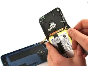
The back camera of the Motorola Moto E6 Play phone is a 13MP, ƒ/2.2, 1.12 µm pixel camera with a LED flash and a PDAF (phase detection autofocus) feature. It also has MPEG-4/H.263/H.264 video capture.

If you are experiencing the ‘Camera Busy’ error, click here for troubleshooting solutions. However, if you are experiencing other issues with the back camera, or the troubleshooting guides do not solve the problem, you may need to replace the camera.


  1. qwn1BQ4hqmdxOhaK
    qwn1BQ4hqmdxOhaK
    BbkgHIeUt2CZ5cdS
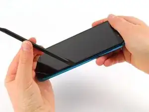
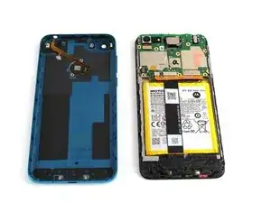
    • Run the halberd spudger along the edges of the device. The back cover should easily pop off.

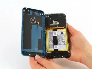
    • Gently remove the back cover. Do not pull hard, as it is still connected to the fingerprint scanner inside the phone.

  2. 6HSWCKewcwPbAIXn
    6HSWCKewcwPbAIXn
    EnMBJDAfMqZhifGi
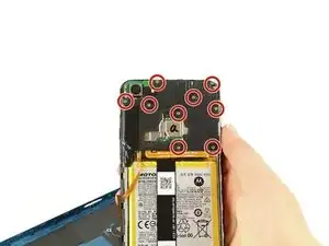
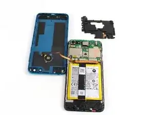
    • To remove the cover on the motherboard, remove the 10 silver 3.90 mm Phillips screws attaching the cover to the board using the Phillips #0 screwdriver.

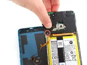
    • One of these ten screws is covered by black tape located at the bottom left corner of the black cover. Peel back the black tape to access this screw.

  3. 5DTDlS6R6YuCvMWq
    5DTDlS6R6YuCvMWq
    JrTNENKTZYexJgtZ
    • With the angled tweezers, remove the black cover to reveal the motherboard underneath.

    • Remove the black piece cover with caution to avoid puncturing the motherboard with the tweezers.

  4. wrokIRJZvyLgiMwW
    wrokIRJZvyLgiMwW
    2PhJpK5qDUDwtjJs
    R5uLfHDK6Day3pd4
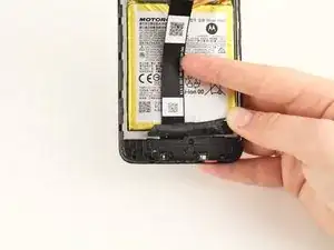
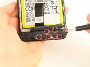
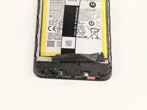
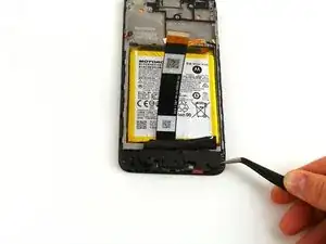
    • The bottom plastic piece covering the daughterboard can be seen by peeling back the tape covering the bottom section of the phone below the battery.

    • To remove the cover, unscrew the six black 3.45 mm Phillips screws holding the cover in place using the Phillips #0 screwdriver.

  5. v6DCyCQLfMPMZFaE
    v6DCyCQLfMPMZFaE
    JQ1A3gcaFTgdHUPU
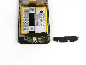
    • Remove the black cover piece using the angled tweezers.

  6. vikVvHLtaVjWqLIl
    vikVvHLtaVjWqLIl
    AXroUcXXrbXPhtQd
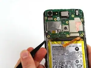
    • Use the angled tweezers to pry off the metal head of the connecting piece from the main motherboard assembly.

  7. RAxmNUhDblp1yyMI
    RAxmNUhDblp1yyMI
    k2JIaiXJiluFhdOG
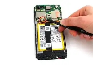
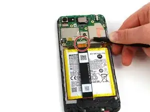
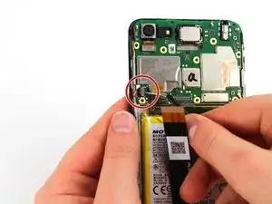
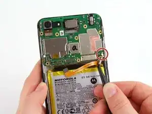
    • Using the angled tweezers, detach the two connectors from the motherboard by pulling the metallic head up and away from the phone.

  8. 1RooyPHoyRCjmidF
    1RooyPHoyRCjmidF
    3mMHHWwiA4Jiu1Pi
    • Use the angled tweezers to flip the black plastic piece from flat to upright.

    • This will allow you to separate the mini connector from the motherboard later.

  9. hiBNnZXrCoSdWtqR
    hiBNnZXrCoSdWtqR
    ltoCHPKQQV2KTYgC
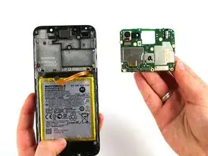
    • Disconnect the rod connected to the motherboard using the angled tweezers.

    • Gently pull the small metal head of the vertically perpendicular from the motherboard with caution to avoid puncturing the board with the tweezers.

  10. 4piq3NpKDWqPIoUM
    4piq3NpKDWqPIoUM
    UslCwZmkkhlyHwQN
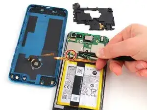
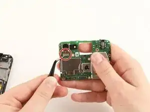
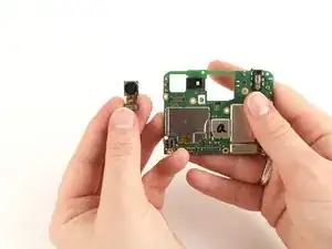
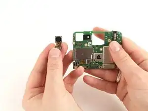
    • Using the angled tweezers, gently lift and pull the tab at the bottom of the camera to remove the back facing camera from the circuit board.

    Great job easy to follow instructions

    jhoneycutt323 -

Abschluss

To reassemble your device, follow these instructions in reverse order.
Charlie Priebe

Mitglied seit: 10/02/20

809 Reputation

0 Kommentare