Einleitung

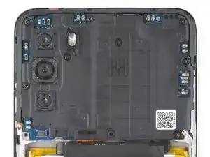
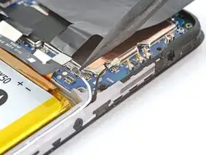
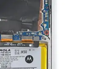
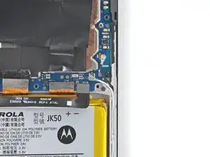
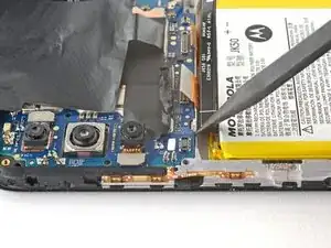
This guide demonstrates how to remove and replace the motherboard assembly on your 2022 Motorola Moto G. This component also contains the rear-facing microphone, front-facing sensors, and heat-dispersion tape.

  1. NKjoEComdv2MdJmd
    NKjoEComdv2MdJmd
    dBPHOnZgJb6xpqGO
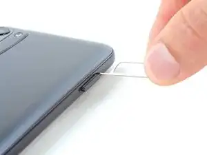
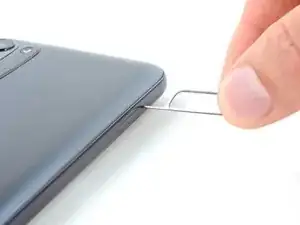
    • Insert a SIM card eject tool or a straightened paperclip into the hole adjacent to the SIM card tray.

    • Press firmly to eject the tray.

  2. D4RxQbF1fTB33daD
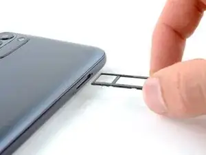
    • Remove the SIM card tray from the phone.

    • When reinserting the SIM card, make sure it's in the proper orientation inside the tray.

  3. pnJcQsI5eCb34MMJ
    pnJcQsI5eCb34MMJ
    dqgqbFkoZEnrdw5i
    • Discharge your battery to 25% or less and completely power off your phone before you begin.

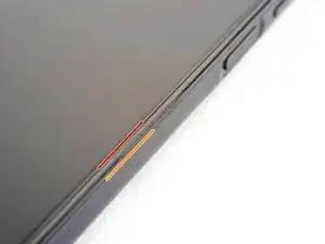
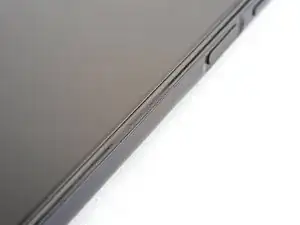
    • Take note of the following seams along the edge of the phone:

    • Screen seam: This seam separates the display panel from the frame. Don't pry at this seam.

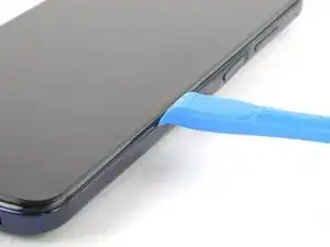
    • Bezel seam: This is where the plastic back cover meets the rest of the phone. It's held in place by plastic clips. This is where you should pry.

  4. p2QPjU1W5ZFUHbaC
    p2QPjU1W5ZFUHbaC
    emVYA3ZFqdlpm3wf
    VTaSCciLcUlM4fNM
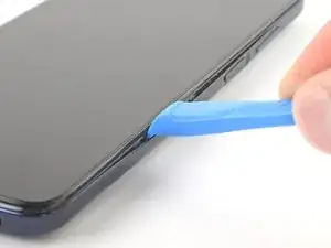
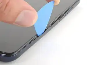
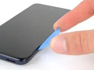
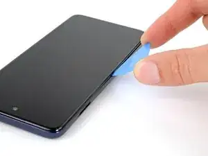
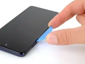
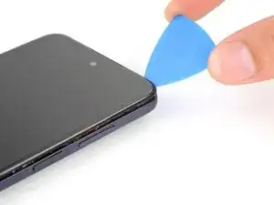
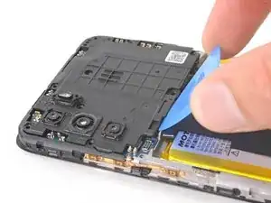
    • Insert an opening tool in the bezel seam halfway between the bottom-right corner of the phone and the power button.

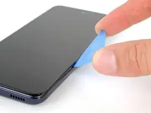
    • Insert an opening pick in the gap you just created.

  5. sdMquhqj1vHiXeHH
    sdMquhqj1vHiXeHH
    F1ZppJrCsJrqdrST
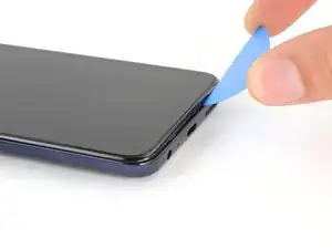
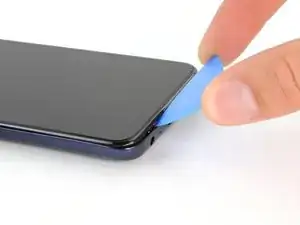
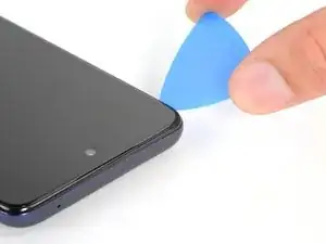
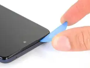
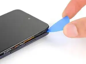
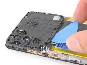
    • Slide your opening pick toward the bottom-right corner of the back cover and release the clips.

    • As each clip releases, you will hear and feel a pop.

    • Don't slide the opening pick near the power or volume buttons.

  6. rLMBJWOYEonqdUWp
    rLMBJWOYEonqdUWp
    CEDDSfjrL3dJhTeb
    • Continue sliding your opening pick towards the bottom left corner to unclip the bottom edge of the back cover.

  7. MqjGiZmgocCFNZoD
    MqjGiZmgocCFNZoD
    IdTOPPFl1bcp2t5g
    gfeeOoudV4eHjSHP
    • Slide your opening pick toward the top left corner to unclip the left side of the back cover.

  8. VSev2IPQuS3iOIen
    VSev2IPQuS3iOIen
    JCNkNPmYbrobeGjc
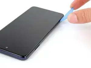
    • Slide your pick around the top left corner and along the top edge to release the clips.

  9. JZrk5GTAVKBOmivU
    JZrk5GTAVKBOmivU
    P21AXlpOYSnVIiJc
    • Slide your pick around the top right corner to release the last clips securing the back cover.

    • Stop before reaching the volume buttons. Your pick may damage their cables.

  10. UdOZASCloZKTlXWy
    UdOZASCloZKTlXWy
    NgVMITKQUHXMkGYf
    INcuBZqA2CdniQEE
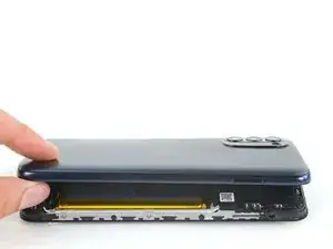
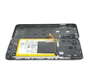
    • Don't try to remove the back cover all the way yet, as it's still connected to the frame by the power button cable.

    • With SIM card slot facing you, swing the back cover open and away from you like you're opening a book.

    • Rest the cover parallel to the frame.

    • Don't twist the screen or move it too far away from the frame to avoid damaging the power button cable.

  11. W4wktAxoXvaC1f5T
    W4wktAxoXvaC1f5T
    uCcOncYVTIBFvoWf
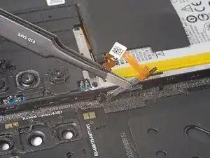
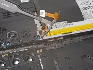
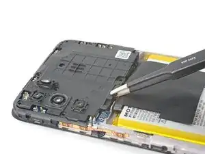
    • A small rubber arm connects the power button to its recess. Use caution to avoid tearing this piece.

    • Use tweezers or your fingers to unhook the power button's rubber arm from its recess and remove it.

  12. JoV3ShXgFTByJEoU
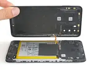
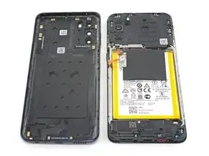
    • You're now left with the back cover.

    • This is a good point to test your phone before sealing it up. Follow this guide to perform a hardware test. Be sure to power your phone back down completely before you continue working.

  13. Lg162OXPZvaDNayS
    Lg162OXPZvaDNayS
    iYTKK6CfPtiFYkuN
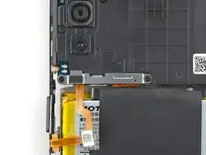
    • Use a PH00 screwdriver to remove the two 3.9 mm-long screws securing the power button cable bracket.

  14. Z5PIqugcTt2S6UgM
    Z5PIqugcTt2S6UgM
    1fT2xwRohAd6OD1p
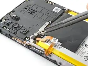
    • Use your fingers or a pair of blunt nose tweezers to grab and remove the bracket from the power button cable.

  15. gVaSod3wAHofDYOJ
    gVaSod3wAHofDYOJ
    YfLChWhEPmtILCrf
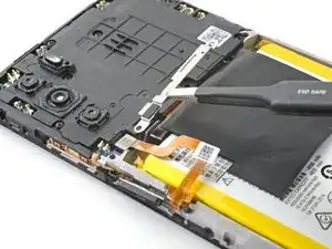
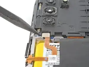
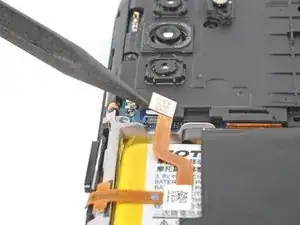
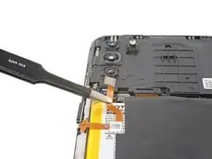
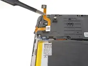
    • Use the pointed end of a spudger to pry up and disconnect the power button's press connector.

  16. cTtduLSI4kHPKXAW
    cTtduLSI4kHPKXAW
    UYREO6ToOBPFIuLn
    • Grab and remove the power button.

    • If you're using tweezers, take care not to puncture the battery—a punctured battery may leak dangerous chemicals or cause a fire.

  17. a4RPQCqSDyIQcDT2
    a4RPQCqSDyIQcDT2
    CYLHrbdbpcjG5iNp
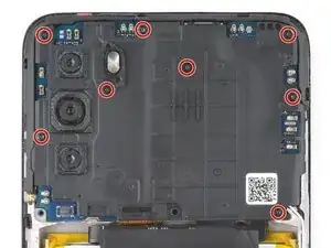
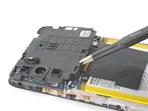
    • Use your Phillips screwdriver to remove the eight 3.9 mm-long screws securing the motherboard cover.

  18. 3OjF5weaLdy3hjiy
    3OjF5weaLdy3hjiy
    GhMbhQoLPQVYPY6i
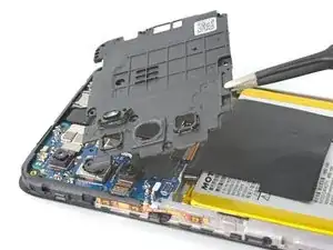
    • Insert an opening pick between the bottom-left corner of the cover and the motherboard.

    • Pry up to release the cover's small clips securing it to the frame.

    • Don't pry against the battery. Use protrusions in the frame for leverage.

    • Work your way around the perimeter to free the cover if it feels stuck.

  19. FSidj6TXerMDEHmV
    FSidj6TXerMDEHmV
    KYy6GbhA4MMmnQnM
    gqVKIyACj24HYbew
    • Grab and remove the motherboard cover from the phone.

    • If you're using tweezers, take care not to puncture the battery—a punctured battery may leak dangerous chemicals or cause a fire.

  20. bNCIZLOP5H3oRxel
    bNCIZLOP5H3oRxel
    VE3iiSVWr36YeBu2
    • Use the pointed end of a spudger to pry and disconnect the battery's press connector.

    • To re-attach press connectors like this one, carefully align and press down on one side until it clicks into place, then repeat on the other side. Don't press down on the middle. If the connector is misaligned, the pins can bend, causing permanent damage.

  21. kchmxQfNLTgLXtVq
    kchmxQfNLTgLXtVq
    dGx6F3nnS56TpQsR
    Nwn1JorGlTYxRwdk
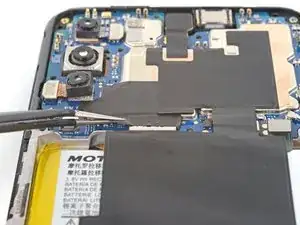
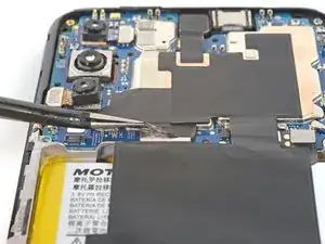
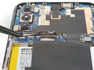
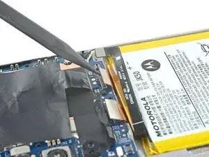
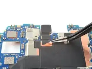
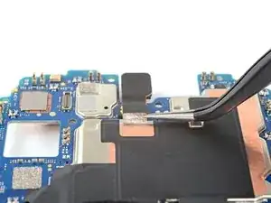
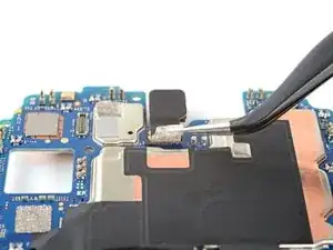
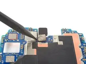
    • Peel the tape from the display connector.

    • If you are using a pair of tweezers, use caution to avoid the battery.

    • If you're having trouble peeling the tape, heat an iOpener and apply it to the tape for 60 seconds.

  22. NQ4R4VPxk5vksgWQ
    NQ4R4VPxk5vksgWQ
    hngiPW6VVfllVysU
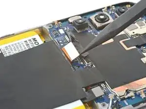
    • Use the pointed end of a spudger to pry and disconnect the screen's press connector.

  23. GLZMQttrhSWPeP2a
    GLZMQttrhSWPeP2a
    AE2kNTaWhKpLt3rf
    FhTCloyPnsXFXOh2
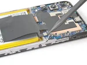
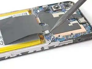
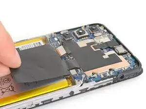
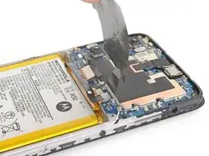
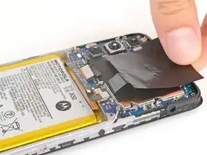
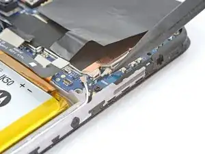
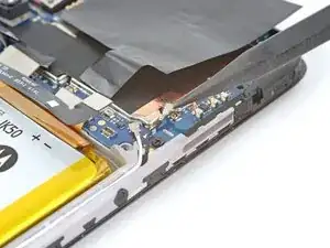
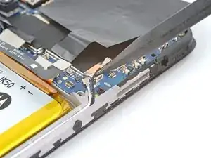
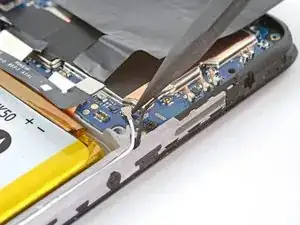
    • Fold the graphite heat film away from the battery to expose the lower section of the motherboard.

  24. NOcpHtvPEqqCdMBS
    NOcpHtvPEqqCdMBS
    OWiqprisoUgAiDXk
    • Use the pointed end of a spudger to pry and disconnect the board cable's press connector.

  25. UZyoVdv4xk2U1fA4
    UZyoVdv4xk2U1fA4
    6xHFnoJMLQi4IJMV
    rDpZhuWufW5rcPjg
    • Use the pointed end of your spudger to pry and disconnect the head of the black antenna cable.

    • Pry on only the metal head of the connector. Avoid lifting the cable itself as much as possible.

    • Free the cable from the clip below the head of the connector.

    • During reassembly, these can be tricky to reconnect. Hold the connector in place over its socket and press down with the flat end of a spudger. The connector should snap into place.

    • During reassembly, make sure to secure the cable to the clip below the head of the connector.

  26. duqgVrGEOTrrlNHI
    duqgVrGEOTrrlNHI
    EJSoZ4L3duUTWGt6
    • Repeat the previous step for the white antenna cable.

  27. nLOGlKbVxhELGaWT
    nLOGlKbVxhELGaWT
    PaOEbSicubbvXDdm
    • Use your Phillips screwdriver to remove the 2.9 mm-long screw from the bottom-right corner of the motherboard.

  28. LRSCnHiXBPXIUiu3
    LRSCnHiXBPXIUiu3
    h5WC1KGZMbIHJUg3
    VoTtFCWPa5ZVmAfh
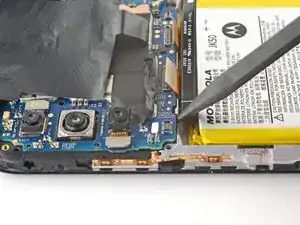
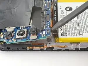
    • Insert the pointed end of a spudger between the lower left of the motherboard and the frame.

    • Lift upward on this bottom edge to free the motherboard from the frame.

    • Don't pry against the battery. Use protrusions in the frame for leverage.

  29. RPWfLp2ECeGCOdZH
    RPWfLp2ECeGCOdZH
    Guy5KIEPVPlAfgbQ
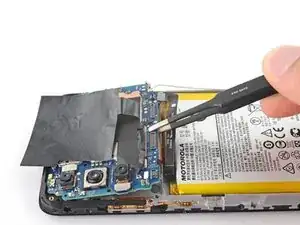
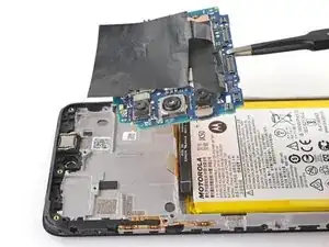
    • Grab the motherboard from the bottom edge and lift it from its recess.

    • Be sure the loose cables don't catch on the motherboard as its removed.

  30. RHMvRgHhWGW1ekvw
    RHMvRgHhWGW1ekvw
    y3ZVdT2TXVhaRPj3
    wlnZhy1MqxU6BLFQ
    • Flip the motherboard over so that the lens of the main camera is facing down.

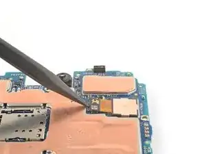
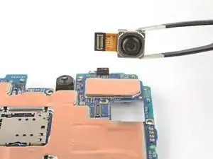
    • Use the pointed end of your spudger to pry and disconnect the main camera's press connector.

    • Remove the main camera from the motherboard.

  31. AnHisRWl62AfUDf4
    AnHisRWl62AfUDf4
    ZXKTsnR1uWIIK4kG
    fRjnoHBGJ6ILvJCL
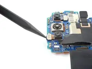
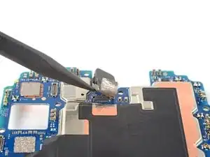
    • Use the pointed end of a spudger to pry and disconnect the macro camera's press connector.

    • The camera may eject from the motherboard. Be careful to not lose it.

    • Grab and remove the macro camera.

  32. KmQO6LvpZEYeqv6p
    KmQO6LvpZEYeqv6p
    qeECPMQLJZqHwfw6
    lR2jCaI1gCVkHNFK
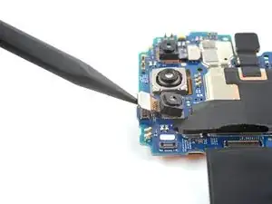
    • Use the pointed end of a spudger to pry and disconnect the depth camera's press connector.

    • The camera may eject from the motherboard. Be careful to not lose it.

    • Grab and remove the depth camera.

  33. kNdTiLDwVhJJicqT
    kNdTiLDwVhJJicqT
    clEGBQUQEuecOSBM
    UFeCL5hh6PHmQNCD
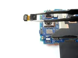
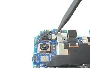
    • Use a pair of tweezers to peel the tape connecting the front-facing camera to the motherboard.

  34. 36teY5vmecWPRYsu
    36teY5vmecWPRYsu
    RlUMBd1vtDjoQnHh
    v4FEQKQZNy1hovyJ
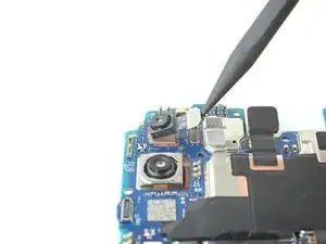
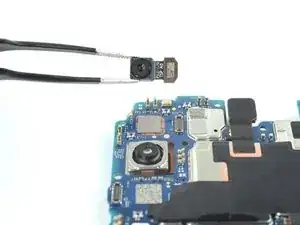
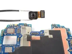
    • Use the pointed end of a spudger to pry and disconnect the camera's press connector.

    • Grab and remove the camera.

  35. 5dEJdWieZCmCNH2O
    5dEJdWieZCmCNH2O
    OpQtxbpfKSpFAvdT
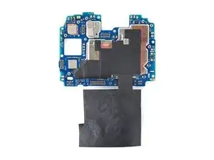
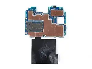
    • All that remains is the motherboard.

Abschluss

Compare your new replacement part to the original part—you may need to transfer remaining components or remove adhesive backings from the new part before you install it.

To reassemble your device, follow these instructions in reverse order. Apply new adhesive where necessary after cleaning the relevant areas with isopropyl alcohol (>90%).

Take your e-waste to an R2 or e-Stewards certified recycler.

Repair didn’t go as planned? Try some basic troubleshooting, or ask our Answers community for help.

Clay Eickemeyer

Mitglied seit: 19/09/22

23447 Reputation

0 Kommentare