Einleitung

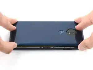
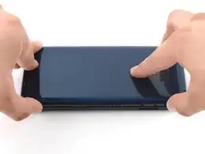
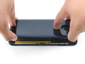
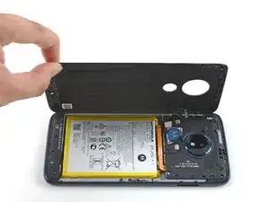
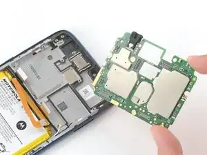
Use this guide to remove or replace the motherboard on your Motorola Moto G7 Power.

You’ll need some double-sided tape (such as Tesa tape) in order to adhere the replaced components.

For your safety, discharge the battery below 25% before disassembling your phone. This reduces the risk of a dangerous thermal event if the battery is accidentally damaged during the repair. If your battery is swollen, take appropriate precautions.

  1. PvVLWquhQVIA4MfH
    PvVLWquhQVIA4MfH
    uQwLmDnMyS1KOuZ2
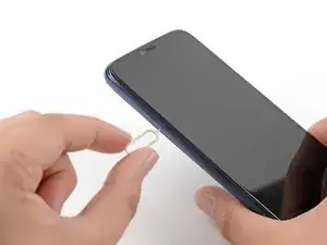
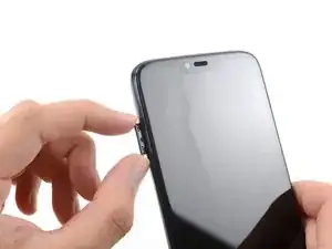
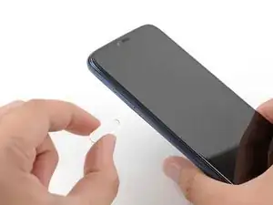
    • Insert a SIM card eject tool into the small hole on the left side of of the phone.

    • Press gently until you feel the SIM card tray pop out slowly.

  2. LwGQG1OK3smEq2tI
    LwGQG1OK3smEq2tI
    rbrqICFiWApQsgW2
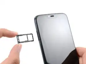
    • Remove the SIM card tray from the phone.

    • When reinserting the SIM card tray, ensure that the hole is on the bottom side.

  3. GHRtjReqBgmkMlvk
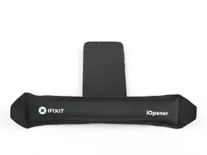
    • Apply a heated iOpener or a heat gun to the bottom edge of the screen for approximately two minutes to help soften the adhesive.

    • A hair dryer, heat gun, or hot plate may also be used, but be careful not to overheat the device—the display and internal battery are both susceptible to heat damage.

    In my case, I heated the iOpener in boiling water for more than 2 minutes, but this did not weaken the adhesive. With the hair dryer it finally worked.

    Elmar -

  4. vs6nAcZXBPjHBurC
    vs6nAcZXBPjHBurC
    dBOx2QqF3tI2TMj3
    QKsGxJsVUEQu2ShM
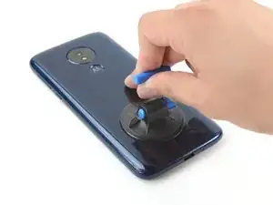
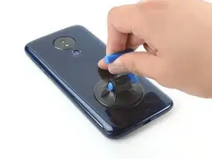
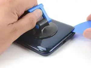
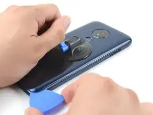
    • Apply a suction cup to the rear cover, as close to the heated edge as possible.

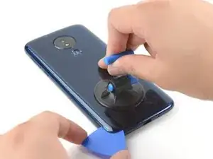
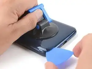
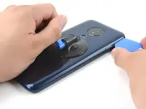
    • Pull up on the suction cup with strong, steady force to create a gap.

    • Depending on the age of your device, this may be difficult. If you have trouble, apply more heat and try again.

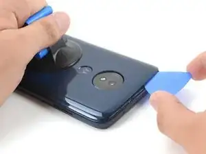
    • Insert an opening pick into the gap you created under the rear cover.

    The suction cup did not stick on the cover, as I increasingly put force on it.

    Elmar -

  5. kYmkAnpJbppMKSHQ
    kYmkAnpJbppMKSHQ
    NSsFuo2dwmRdpQxf
    • Slide the pick along the bottom of the gap to slice through the adhesive securing the rear cover to the midframe.

    • After being cut, the adhesive will sometimes stick back together as it cools. To prevent this, you can leave the pick in this edge after cutting, and continue the next steps with a new pick. Repeat this with each edge, leaving a pick and continuing with a new one.

    I managed to put in the picks one by one. This worked fine.

    Elmar -

    No way you can get a pick in. There is no movement at all in the cover, even if I fry the device!

    emere -

  6. 1gipLZ3cXpDoJose
    1gipLZ3cXpDoJose
    SAQoAPhbhnOjFTJM
    • Slide the pick along the gap on the same side of the phone as the SIM card tray to slice through the adhesive securing the rear cover to the midframe.

    Just to mention it... It is a good idea not to start directly at the SIM slot...it might break.

    Elmar -

  7. cFDPgtRSbcHATRgk
    cFDPgtRSbcHATRgk
    iICjBMPqrDfcFZF4
    • Slide the pick along the gap at the top of the phone to slice through the adhesive securing the rear cover to the midframe.

  8. f6gFDKAdv2LPCdab
    f6gFDKAdv2LPCdab
    yNfkqprn3X2CBURo
    SY4WraWphSa4dUcZ
    • Slightly lift up the rear cover starting from the right side.

    • This will prevent damage to the fingerprint sensor connector under the left side of the rear cover.

    • If lifting the rear cover is difficult, slice through any remaining adhesive with an opening pick. Reapplying the iOpener can also help weaken the adhesive.

    • Use a finger to press down on the fingerprint sensor until it separates from the rear cover.

    I had to cut some of the adhesive on the left side of the phone also. Fortunately, there is nothing sensitive close to the edge and everything is covered with a shield.

    Zackery Ooms -

  9. ACbURrZQ4cMru1Mr
    ACbURrZQ4cMru1Mr
    vR6bLjLtvLvVBGt1
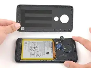
    • Remove the rear cover, taking care not to damage the fingerprint sensor.

    • During reassembly, follow this guide to install custom-cut adhesives for your device.

  10. XKlcv1MTypTSPKrF
    XKlcv1MTypTSPKrF
    DDNDpmTWwBVekZXf
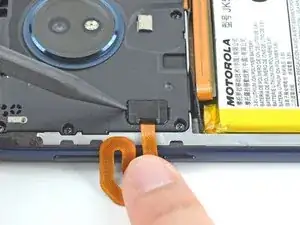
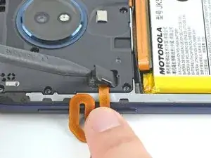
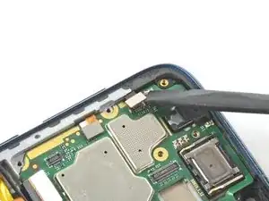
    • Insert the pointed end of a spudger into the divot at the top of the fingerprint sensor connector cover.

    • Gently pry the cover open.

    • Remove the cover.

  11. FhPFXsZdddIAajaF
    FhPFXsZdddIAajaF
    OEaeTyrXdJt5drPW
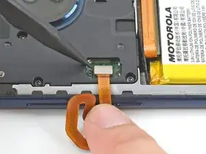
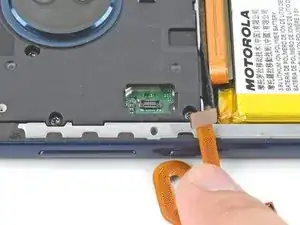
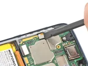
    • Use the pointed end of a spudger to pry up on the fingerprint sensor connector to disconnect it.

  12. qtEnp4iwLLRhemPh
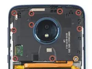
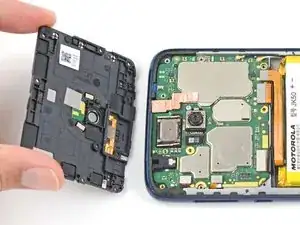
    • Use a T5 Torx screwdriver to remove the ten screws securing the motherboard cover to the midframe:

    • Nine 3.5 mm screws

    • One 3.0 mm screw

  13. MU5nnDvwwakwABLw
    MU5nnDvwwakwABLw
    T22FBiIt4a4WLOVT
    rym6WMo6i14R4dxX
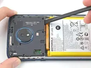
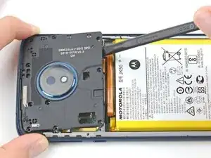
    • Insert the flat end of a spudger under the motherboard cover.

    • Pry the motherboard cover upwards to lift it from the motherboard.

    • Remove the motherboard cover.

  14. KSdYijMFjLIgFFYm
    KSdYijMFjLIgFFYm
    OOMIfCvVXtVqJbQ2
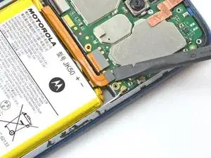
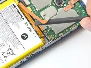
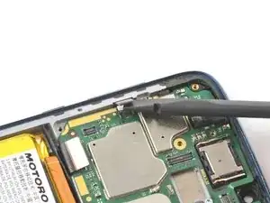
    • Use the flat end of a spudger to pry up on the battery connector to disconnect it.

  15. jl6NLtyp5wTJaUXq
    jl6NLtyp5wTJaUXq
    SHUJSkdkapHQkVHL
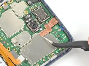
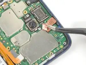
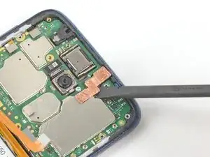
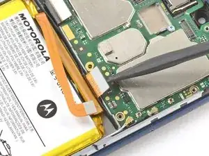
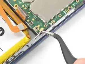
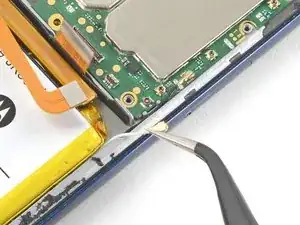
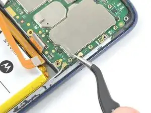
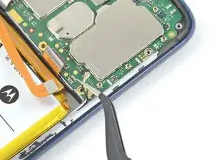
    • Use a pair of tweezers to gently peel back the bottom of the copper sheet covering the metal shield below the front-facing camera.

  16. bOCQYVFpVXcxgOCJ
    bOCQYVFpVXcxgOCJ
    lAgfRlFiYlJdaBhT
    oAGAC1M1ooX3HGjM
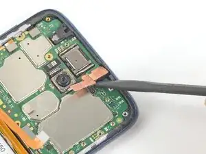
    • Use the flat end of a spudger to pry up on the front-facing camera's connector to disconnect it.

    • Remove the front-facing camera.

  17. mEXKjlJEmFGC1tXI
    mEXKjlJEmFGC1tXI
    TFbLe4syZMd1dXoZ
    1Na5BQDy5CFmS5NZ
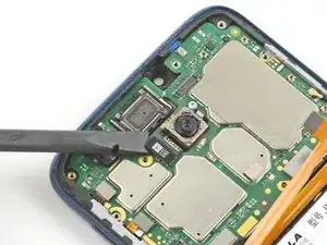
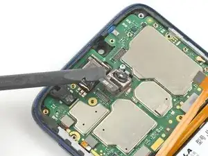
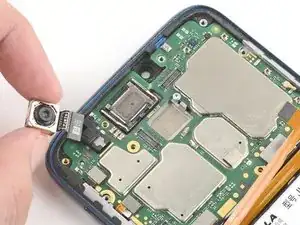
    • Use the flat end of a spudger to pry up on the rear camera connector to disconnect it.

    • Remove the rear camera.

  18. vYwDZvxQA2syOPHu
    vYwDZvxQA2syOPHu
    ZUB5YsLcxVx2Ew2W
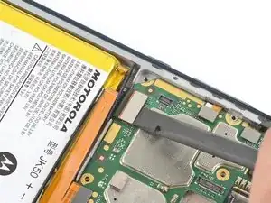
    • Use the flat end of a spudger to pry up on the display cable to disconnect it.

  19. UmUeFU3UKEIbYFqL
    UmUeFU3UKEIbYFqL
    B4MgoiSSJ4mKgSb1
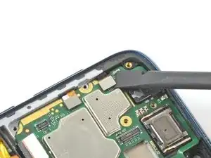
    • Use the flat end of a spudger to pry up on the upper side button connector to disconnect it.

  20. xfMTDMYFswQ5kd2W
    xfMTDMYFswQ5kd2W
    jolDl5g5hHsjduBG
    • Use the flat end of a spudger to pry up on the lower side button connector to disconnect it.

  21. VUxYtRBuDhTpFKIR
    VUxYtRBuDhTpFKIR
    3vOiMFetvkDpToQT
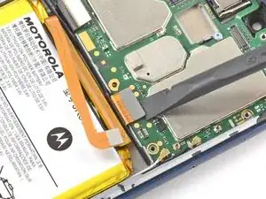
    • Use the flat end of a spudger to pry up on the interconnect cable connector to disconnect it.

  22. wSYPcW36UQSftKw5
    wSYPcW36UQSftKw5
    d2QDQGMkAMOZUTbc
    • Follow this guide for in-depth instructions on how to disconnect a coaxial connector.

    • Slide one of the tweezer's tips under the white wire until it's snug against the connector, and pry straight up from the board.

    • To reinstall, hold the connectors in place and gently press them straight down. The connectors “snap” into their sockets much like the metal snaps on a jacket.

  23. srYUpkcLqIe2TyyU
    srYUpkcLqIe2TyyU
    PsMRSHmI1OvREGf5
    • Slide one of the tweezer's tips under the black wire until it's snug against the connector, and pry straight up from the board.

  24. i2sPtQgPCHcsPGkQ
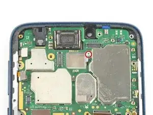
    • Use a T5 Torx screwdriver to remove the 3 mm screw securing the motherboard to the midframe.

  25. IyacQ1AAUL3IkpbT
    IyacQ1AAUL3IkpbT
    ZwCKZigUB3Tm5CMo
    G4LRjOeu31XdD6pP
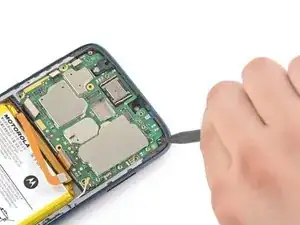
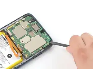
    • The SIM card tray also secures the motherboard to the midframe, so ensure that it has been removed before this step.

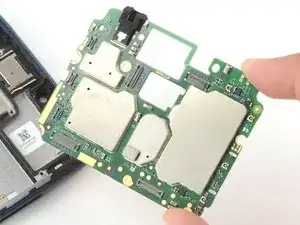
    • Insert the pointed end of a spudger under the top right corner of the motherboard to lift it from the midframe.

    • Remove the motherboard.

Abschluss

To reassemble your device, follow these instructions in reverse order.

Take your e-waste to an R2 or e-Stewards certified recycler.

Repair didn’t go as planned? Try some basic troubleshooting, or ask our Motorola Moto G7 Power Answers community for help.

Compare your new replacement part to the original part—you may need to transfer remaining components or remove adhesive backings from the new part before you install it.
Clay Kim

Mitglied seit: 16/02/21

6899 Reputation

0 Kommentare