Einleitung

If your Motorola V551 Cellphone screen non-operational, it is likely that the screen is in need of repair. In order to remove and replace the screen, follow these steps.

The screen is the most important feature of a cell phone to the user. Without the ability to see the actions you are taking, a phone is meaningless. A faulty screen will not display anything on the phone.

Before using this guide, inspect the other components and their connections to the motherboard. The problem could be a component being unplugged from dropping the phone.

Be cautious of your surroundings due to the sensitivity of the cellarer device. Foreign objects can be detrimental to the life of a cell phone. Ensure the cellphone is fully powered off and not plugged in due to electrical reasons.

The link below is a forum provided by a third party for users with similar problems.

https://cellphoneforums.net/motorola/t23...

  1. 5DJPRKqdrNLtNsTL
    5DJPRKqdrNLtNsTL
    CGWwZZtp3VtFyqyJ
    MZoj2hvO66Caodpy
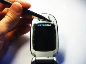
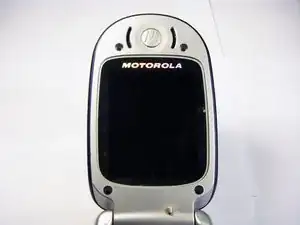
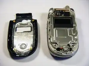
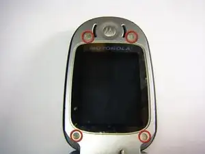
    • On the phone's face, remove the four rubber caps from the screw covers using a spudger.

  2. 6ktWOaVGgIll5lPb
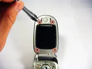
    • Unscrew the four cover screws using a T6 Torx screwdriver, turning counterclockwise.

  3. h4mVMsrNi2PeUokl
    h4mVMsrNi2PeUokl
    I4xAQoashFrVaVKb
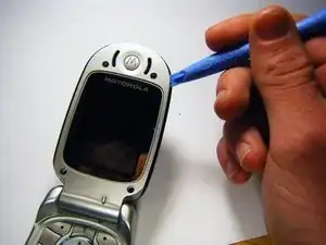
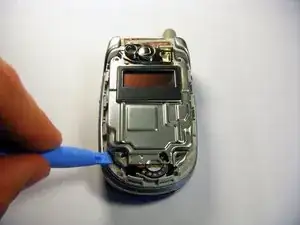
    • Loosen and remove the protective cover using a plastic opening tool.

  4. bER1oLtYqdU4LUPv
    bER1oLtYqdU4LUPv
    vONeYK4R1VeItf2f
    • Gently loosen the second protective cover with the plastic opening tool.

    Do not pry from the top or bottom of the metal cover. There are a pair of 1/4" long openings on either side of the metal cover at the midpoint of the case. The plastic teeth which lock into the openings must be withdrawn. I used the point of cuticle sissors to get behind the metal strip under each tooth and pull outwards a small distance to release each tooth. The sides of the cover will spring up.

    Fonce -

  5. o5qRPRpbLQs3hce2
    o5qRPRpbLQs3hce2
    2flpCsfMZZcePQfx
    U156s5j5AOxduucm
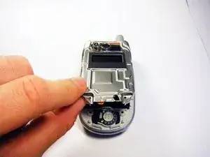
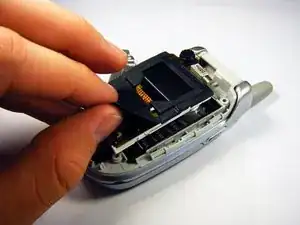
    • Carefully remove the protective cover from the circuitry.

    • Slowly peel the black rubber gasket off of the circuit board.

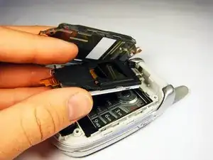
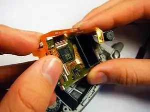
    • Carefully move the camera out of the way using your hand.

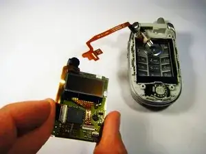
    • Use a flat tool to disconnect the upper and lower circuit boards.

  6. j4mGGe1DvJpLNrC6
    j4mGGe1DvJpLNrC6
    LPAmyRDAhAU1AdSQ
    oLtugVHUXAYkqWy2
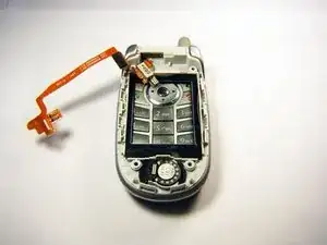
    • Gently slip the copper strip out from under the circuitry by using your hand.

Abschluss

To reassemble your device, follow these instructions in reverse order.
gregatron

Mitglied seit: 29/10/09

105 Reputation

0 Kommentare