Einleitung
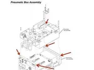
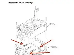
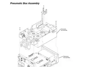
The pneumatic box is a very important removal step and requires the user to be very careful when removing. It is important to note that the guide removal begins on page 44 of the service manual. When reinstalling, the user must read the reinstalling instructions located on page 45 of the service manual.
Werkzeuge
-
-
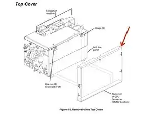
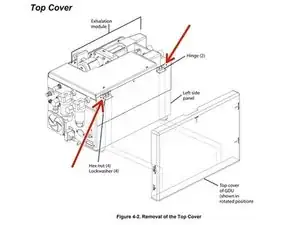
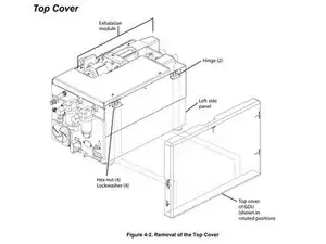
Remove the four hex nuts and lock washers (two at each hinge) that secure the cover to the hinges on the left side of the pneumatic box.
-
-
-
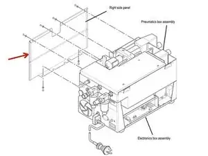
Carefully place the GDU on its right side with the front of the GDU facing you.
-
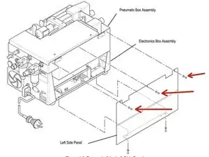
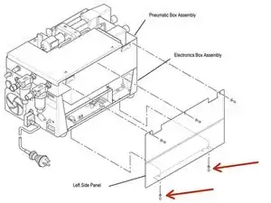
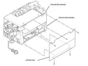
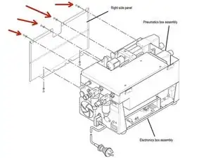
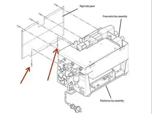
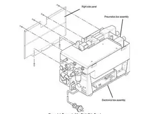
Remove the three screws and washers at the top edge of the left side panel.
-
-
-
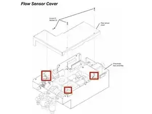
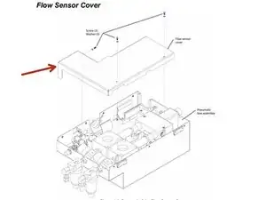
Remove the three screws and washers that secure the flow sensor cover to the pneumatic box assembly. Retain the hardware for re-assembly.
-
-
-
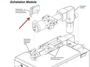
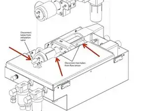
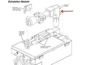
Disconnect the tubes from both sides of the flow sensor and the two tubes from the exhalation valve.
-
-
-
Remove the two screws and washers (back corners), one screw and washer (exhalation module support bracket), and two standoffs and washers (front corners) that secure the pneumatic (upper) box assembly to the electronic box assembly. Lift the Pneumatics Box and carefully tilt to one side.
-
-
-
Remove cables from connectors J1, J2, J3, J4, J5, and J6 on the main PCB (4 connectors are not shown due to being blocked by the side panel). Note the position of these connectors for re-assembly.
-
-
-
If not already detached, remove the heater cables from J5 and J6 on the DC-DC power supply PCB.
-
To reassemble your device, follow these instructions in reverse order.
