Einleitung

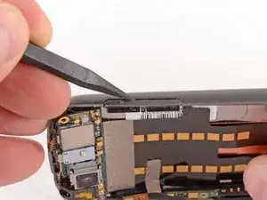
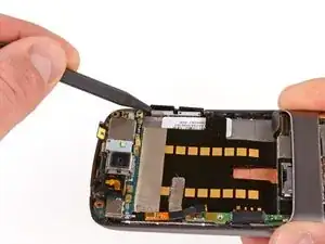
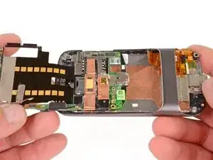
installing the front speaker

  1. uLlMFMhZqIIv3caX
    uLlMFMhZqIIv3caX
    VvvWIQV4IhighMT5
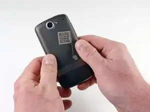
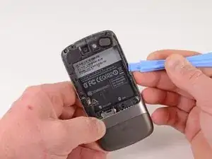
    • Using two fingers, push up on the rear cover.

  2. W1WIrx2VbRpWGxKX
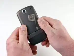
    • The rear cover slides up and off.

  3. DXcrcy1T6vY3HEWU
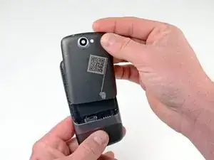
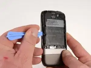
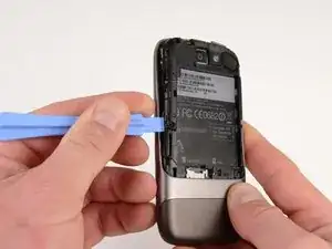
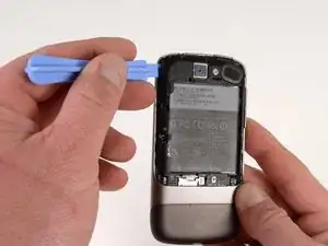
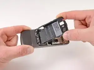
    • Using the plastic opening tools, pry the left bottom corner of the battery up.

  4. oHgCrbeRKYNsKGyW
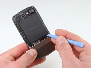
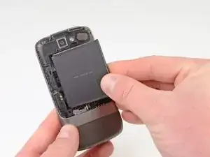
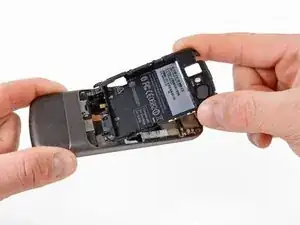
    • Pull the battery up and out.

  5. LEk4TtIlJpNBnkLG
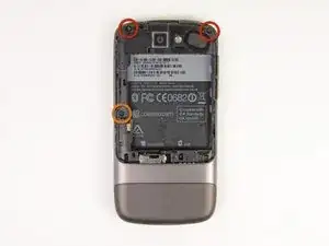
    • Remove the two Torx T5 screws.

    • Remove the one Philips #00 screw.

    #0 Phillis screw

    skuhry -

  6. AVHTJRTTmHURrqWr
    AVHTJRTTmHURrqWr
    DFrOaUx4hjItP3UE
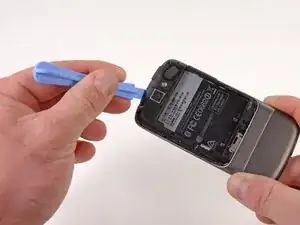
    • Using the plastic opening tool, pry up the battery housing upwards.

    • Push pry tool down, undoing the plastic tab.

  7. fBve6wgcClcIKG5q
    fBve6wgcClcIKG5q
    d6FAlJcMTtpDLdHk
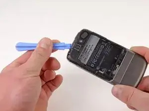
    • Pry the upper left tab open on the battery housing.

  8. ZYjsMVCidphXMyax
    ZYjsMVCidphXMyax
    XHJ5vDEoxHwmFQDR
    • Pry the top tab of the battery housing.

  9. IqJXdHPhdvbQoDe2
    IqJXdHPhdvbQoDe2
    EP3MoAITbalwK6PZ
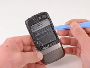
    • Pry the right side tab of the battery housing.

  10. crX1ZluSiKZIiaWi
    crX1ZluSiKZIiaWi
    RZnGp4KEQgTZDiAU
    • Pull up on the battery housing.

    • Slide the battery housing out to remove it.

  11. UFirPLBU1AW3ChVh
    UFirPLBU1AW3ChVh
    Ne4pArRGLdGCEP4N
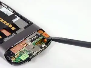
    • Insert the spudger under the connector.

    • Push the spudger up and twist to release the connector.

    • Repeat for the next connector.

  12. AjvJ6KItQRaoqGNP
    AjvJ6KItQRaoqGNP
    maZteloVSJE1k2mn
    T21cyQoNkFVPojGx
    • Push on the USB port to expose the black connector.

    • Use the spudger to pry the connector upwards.

    The philips screw holding down the logic board (at the lower right corner in the picture) has to be removed before the board can be pushed back.

    Mark -

  13. ZNaPUfgJIlwlygAJ
    ZNaPUfgJIlwlygAJ
    2S2VWCCSdNDtB2CI
    • Place the spugder under the antenna connector.

    • Pry connector up vertically.

  14. uGR23MrK6pWwqWWj
    uGR23MrK6pWwqWWj
    uU3IVwyOknfoLpZZ
    jCXY2O25hZgL6LpO
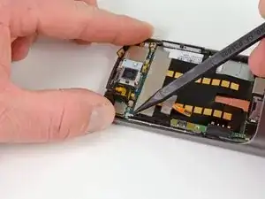
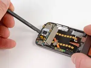
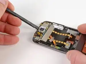
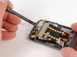
    • Insert the spudger into tab above the camera.

    • Slide upwards until the board detaches from the case.

    A philips screw holding down the upper logic board (in the lower left corner of the picture) must be remobed before the board can be detached.

    Mark -

  15. 2ambQ1RmVnjrJmBd
    • Press the pointed tip of the spudger into the space below the button assembly.

    • Wiggle the spudger tip towards the outside of the button.

    • The button assembly is under some tension and may fly off.

  16. 5HgQCEcgyLAsdQAH
    • Push the pointed tip of the spudger into the base of the side button board.

    • Lift up, the board will disconnect from the case.

  17. pwjOhM1Mki4BYWqU
    pwjOhM1Mki4BYWqU
    TntFBiZHIMB6Kspa
    x4U3c2KkE4KPHjgy
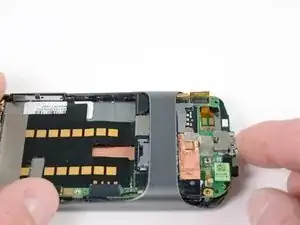
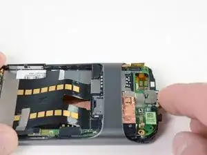
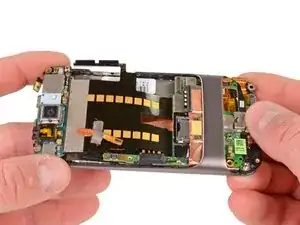
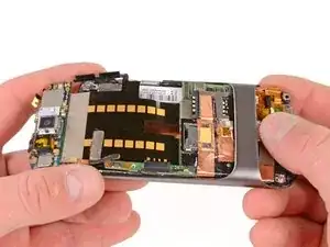
    • Push on the lower motherboard until it slides under the case support.

    • The motherboard assembly comes out as a single piece.

    • Save the small black rubber rectangular sound guide under the motherboard, to replace over the microphone.

    Be carefull not to tear the home button cable that is in the top right corner!!

    zack -

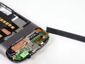
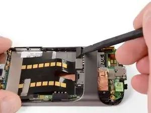
  18. L2qLQFgGPShWqmmI
    • Using the spudger, pop up the end of the speaker.

Abschluss

To reassemble your device, follow these instructions in reverse order.

Niklas Johnson

Mitglied seit: 01/02/12

1207 Reputation

0 Kommentare