Einleitung

  1. dF5vgBKtDeDCgy5j
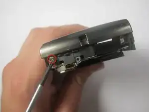
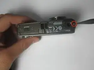
    • With the lens facing forward, remove the one 4.2 mm screw on the bottom right hand corner of the camera.

  2. 4yvPOlgOvuVqrGWp
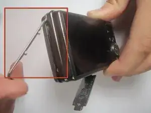
    • Remove the chrome side cover from the body of the camera.

  3. nOETQCWmtSKsmXPM
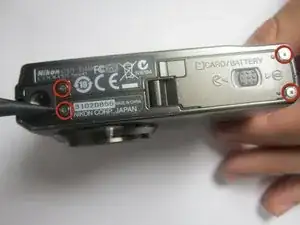
    • Remove the four 3.2 mm screws on the bottom of the camera.

  4. b5WPGVbBEEMW5Yuf
    b5WPGVbBEEMW5Yuf
    ZYHKgA2XZpesrkKn
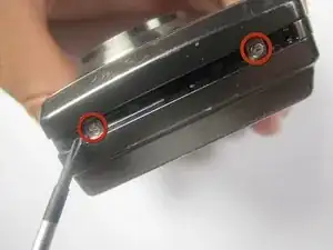
    • Remove the two 3.2 mm screws from the right side of the camera (with lens is facing forward)

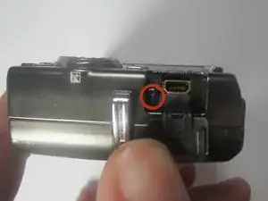
    • Remove the one 3.2 mm screw from the left side of the camera (with lens facing foward)

  5. XnAbZBfC2vphNWbX
    XnAbZBfC2vphNWbX
    CLTpJKr42hgQ1jIH
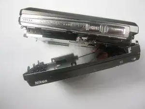
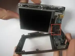
    • Gently separate the back cover from the body of the camera.

    • The back casing will still be connected to the circuit board by a ribbon

  6. co1EBXQxyPJNnq3C
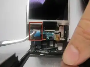
    • Use the tweezers to disconnect the ribbon from the circuit board.

  7. US1jT1loTAgA1lAI
    • Remove the one 2.6 mm screw from the left side of the camera (with the lens facing forward)

  8. IaRylZnmgRA6KZqt
    IaRylZnmgRA6KZqt
    GcK22ZnivtyVaG4A
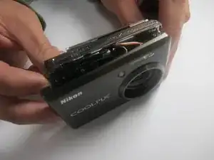
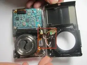
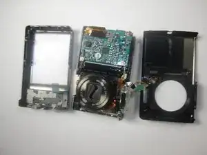
    • Gently separate the front cover from the body of the camera.

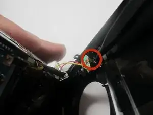
    • The front casing will still be connected to the circuit board by a few wires

  9. s3g2LX2YPtAEjPsZ
    • Remove the two 3.2 mm screws that hold the flash to the front cover.

  10. BrIV4cZJF2BbLwmb
    BrIV4cZJF2BbLwmb
    CMtRulMVujKeDjih
    FTZp6YiiCZWZS4ly
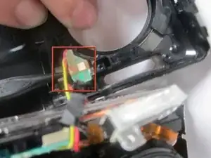
    • Use the Spudger to remove the copper colored light bulb clip.

    • Remove the front cover entierly from the camera body.

Abschluss

To reassemble your device, follow these instructions in reverse order.
andreas anggasastra

Mitglied seit: 15/09/11

116 Reputation

0 Kommentare